5.4 Mounting the protective double bushing on the protective housing
During assembly, the connection cables are routed through the supplied protective dou‐
ble bushing and connected to the device in the protective housing.
If the Ethernet interface is not used, you must close off the free feedthrough in the pro‐
tective double bushing with the supplied dummy plug.
NOTE
Use connection cables with a sufficient length.
NOTICE
The power supply must be disconnected when attaching and detaching electrical con‐
nections.
NOTICE
Do not install O-rings using sharp or pointed tools. The O-rings seal the protective dou‐
ble bushing towards the outside and therefore guarantee the enclosure rating.
5.4.1 Assembly with use of the Ethernet connection
Noting the MAC address
NOTE
The MAC address for the Ethernet interface is located on the type label, see "Type
label", page 10. The address is partially or completely covered when the device is
mounted on a bracket.
Make a note of the MAC address and the name of the reading station.
Mounting the protective double bushing on the protective housing
Assembly is described on the basis of the protective housing for bar code scanner with
front reading window. Assembly of protective housings for bar code scanners with oscil‐
lating mirror and side reading window takes place analogously.
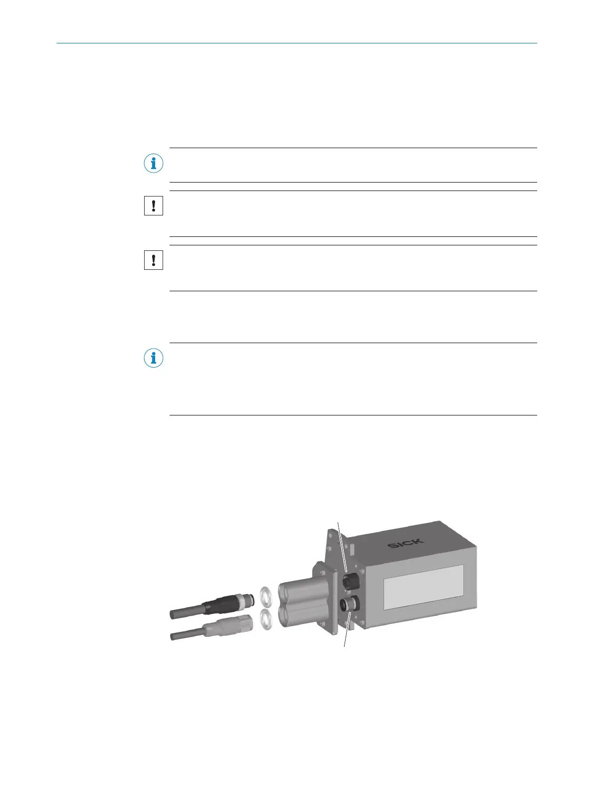
Component overview
Figure 12: Assembly of IP69K protective housing, with use of the Ethernet connection
1
Connection cable for “Ethernet” connection
2
Plug connector of connection cable for “Ethernet” connection
3
O-ring 11.0 mm x 4.0 mm
4
Protective double bushing
5 MOUNTING
20
T E C H N I C A L I N F O R M A T I O N | CLV62x, CLV63x and CLV64x with IP69K Protective Housing 8021479/0000/2018-03-12 | SICK
Subject to change without notice

 Loading...


