times, such as photoelectric sensors or incremental encoders, enable reading pulses
independent of the control. The reading results are provided for further processing by
the data interfaces.
In principle, the codes can be recorded on any side on still or moving objects in a con‐
veyor system (single-side reading).
By combining several devices, it is possible to record several sides in one passage
(multi-side reading).
To record the codes, the device generates a scan line (line scanner).
When designed as a grid scanner, the device generates eight scan lines which are off‐
set parallel to each other.
Line scanner with oscillating mirror
The oscillating mirror also moves the scan line vertically to the scan direction from the
resting position to both sides with a low oscillation frequency. This means that the
device can also scan larger areas for bar codes.
NOTE
When starting up the device, the oscillating mirror may cause increased volume devel‐
opment.
The length of the scan line that can be used for evaluation (reading field height) is
dependent on the reading distance due to the V-shaped light emission.
The light pattern reflected by the bar code is recorded, processed and decoded. To con‐
trol this process, external sensors provide information about the reading pulse and the
conveyor speed (increment). The read results are released to the device's data interfa‐
ces and forwarded to a host/PC.
Detailed wiring of the device and the connections to the host/PC and the external sen‐
sors are described in chapter Electrical installation.
NOTE
The CDB620 connection module with additional circuit board ( see "Connecting connec‐
tion modules to devices with heating", page 40) or the CDM420 connection module
with additional terminal ( see "Connecting the supply voltage", page 43) is to be used
for devices with heating.
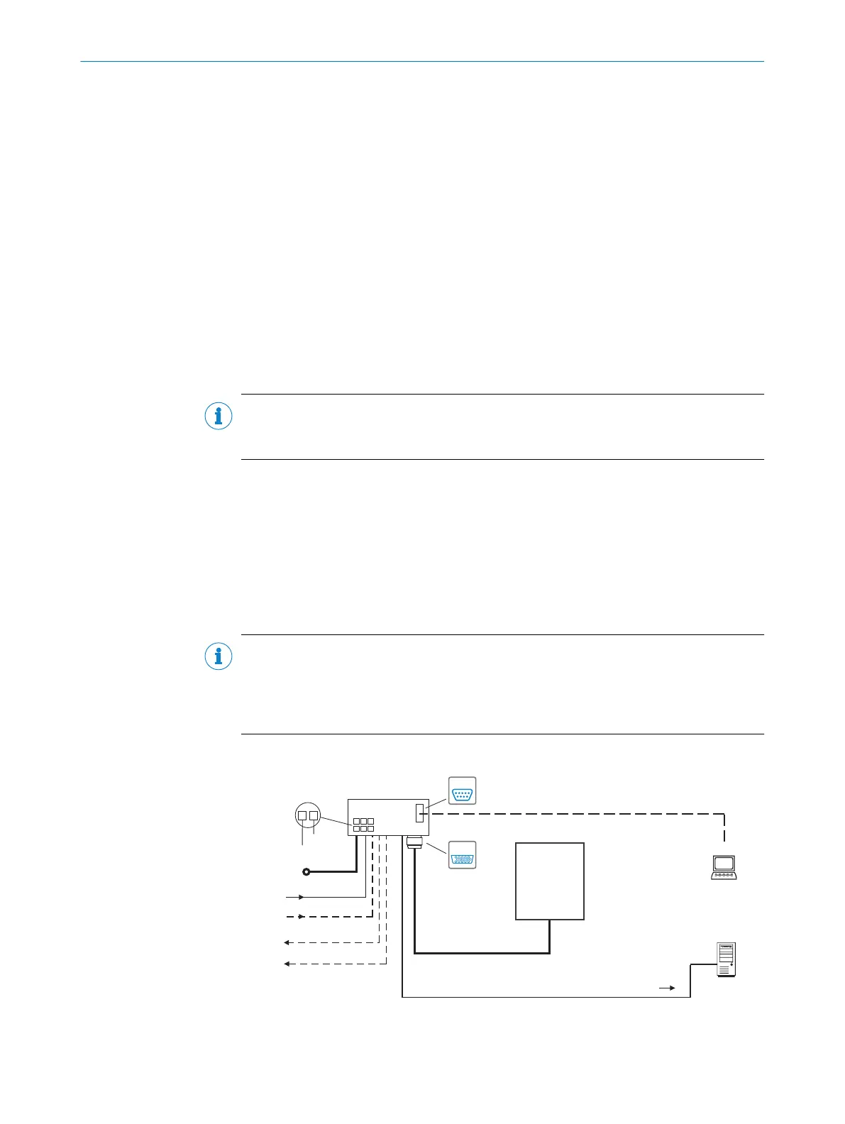
Block diagrams
Input 2
(e.g. incremental encoder)
Input 1
(e.g. external read cycle)
Output 1
(e.g. LED)
Output 2
(e.g. LED)
CLV6xx
“Serial RS-232/RS-422/485” (Host)
CDB620/CDM420
SerialSerial
Configuration
Diagnostics
SOPAS ETSOPAS ET
SerialSerial
“Power/SerialData/CAN/I/O”
(Aux, Host)
...
...
1
2
DC 18 V ... 30 V
GND
HOST
PC
Further data
processing
“Serial RS-232” (Aux)
DC 18 V ... 30 V
Switching inputs/outputs = digital
Reading result
Figure 6: Facilities for connecting CLV63x-65x, standard version
PRODUCT DESCRIPTION 3
8019588/2017-01-20 | SICK O P E R A T I N G I N S T R U C T I O N S | CLV63x, CLV64x, CLV65x
17
Subject to change without notice