NOTICE
Risk of damage to the internal interface modules!
If the serial data interfaces are wired incorrectly, then electronic components in the
device could get damaged.
b
Observe the information on wiring.
b
Carefully check the wiring prior to switching on the device.
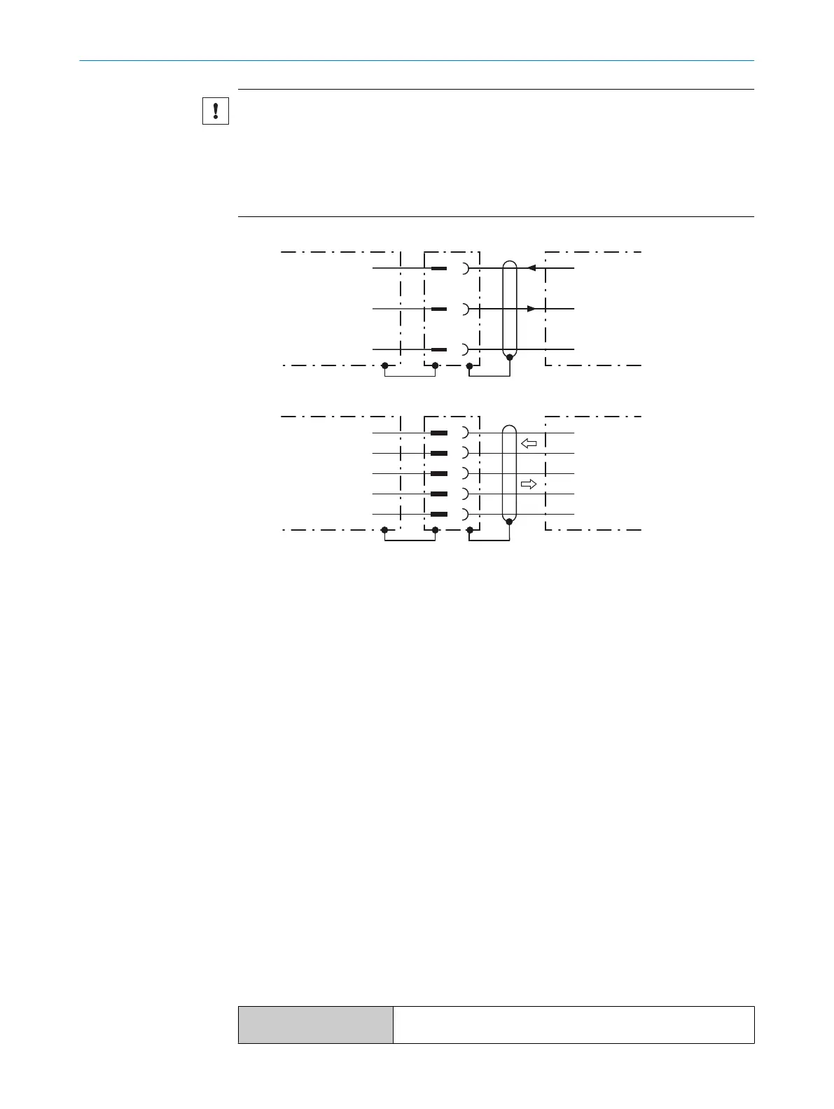
RS-232
!
"
§
Device 1 Host
TxD
RxD
GND
RxD
TxD
GND
RS-422
$
%
&
/
(
Device 1 Host
RD+
TD+
RD‒
TD‒
GND
TD+
RD+
TD‒
RD‒
GND
Figure 39: Internal circuitry for RS-232 and RS-485 data interfaces
1
Device
!...§
Pin assignment: See RS-232 pin assignment for the respective device
$...(
Pin assignment: See RS-422 pin assignment for the respective device
Termination of the RS-422 data interface
Termination of the data interface can be implemented in the connection module via
switches.
Additional information on this can be found in the operating instructions for the relevant
module.
6.6.3 Wiring the CAN interface
If the wiring of the CAN interface is carried out via a connection module, then the rele‐
vant operating instructions of the module used must be followed.
6.6.4 Wiring digital switching inputs
Physical switching inputs on the device
The physical switching inputs can be used for starting and/or ending the reading pulse
or for feeding an incremental signal.
Depending on the device, there are different number of switching inputs available on
the connections, see "Pin allocation of the connections", page 36.
Table 9: Characteristic data for the switching inputs
Switching behavior Power at the input starts the internal reading interval of the device
(default: active high, debounce: max. 30 ms (standard))
ELECTRICAL INSTALLATION 6
8014396/ZMG8/2017-07-04 | SICK O P E R A T I N G I N S T R U C T I O N S | CLV69x
47
Subject to change without notice