Properties Opto-decoupled
Reverse polarity protected
Electrical values The electrical values are identical for all switching inputs.
Low: |V
in
| ≤ 2 V; |I
in
| ≤ 0.3 mA
High: 6 V ≤ |V
in
| ≤ 32 V; 0.7 mA ≤ |I
in
| ≤ 5 mA
Signal 3
3.32K
6.64K
"
§
$
Sensor GND
V
S
2
V
S
V
S
V
in
5
!
PNP sensor 1
GND
Switching input 4
GND
V
S
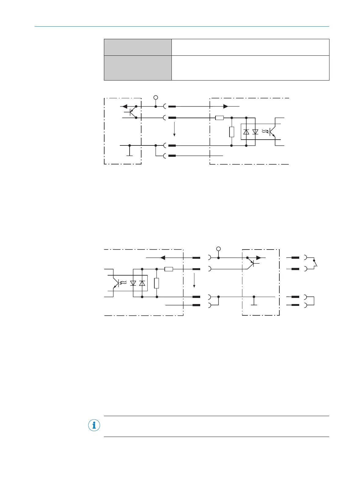
Figure 40: Wiring of a switching input with external PNP sensor
1
PNP sensor
2
Supply voltage V
S
3
Input signal
4
Switching input (“Sensor 1” or “Sensor 2”)
5
Input voltage V
in
!...$
For pin assignment, see respective device
SwitchPNP sensorSwitching input
Signal
3.32K
6.64K
1
2
3
4
1
2
3
4
Sensor GND
U
V
U
V
U
V
U
e
GND
GND
Figure 41: Wiring of a switching input with external, triggered PNP sensor
1
Supply voltage U
s
2
Signal line (e.g. “Sensor 2”)
3
SensGND
4
GND
Extension: additional logical switching inputs in the device in the case of physical
“external” switching inputs on the optional connection module
Thanks to the optional CMC600 parameter memory module, the two external switching
inputs “External input 1” and “External input 2” on the relevant terminals in the connec‐
tion module are additionally available.
NOTE
These two external switching inputs are not suitable for time-critical applications.
If the wiring of the inputs is carried out via a connection module, then the relevant oper‐
ating instructions for the module must be followed.
6 ELECTRICAL INSTALLATION
48
O P E R A T I N G I N S T R U C T I O N S | CLV69x 8014396/ZMG8/2017-07-04 | SICK
Subject to change without notice