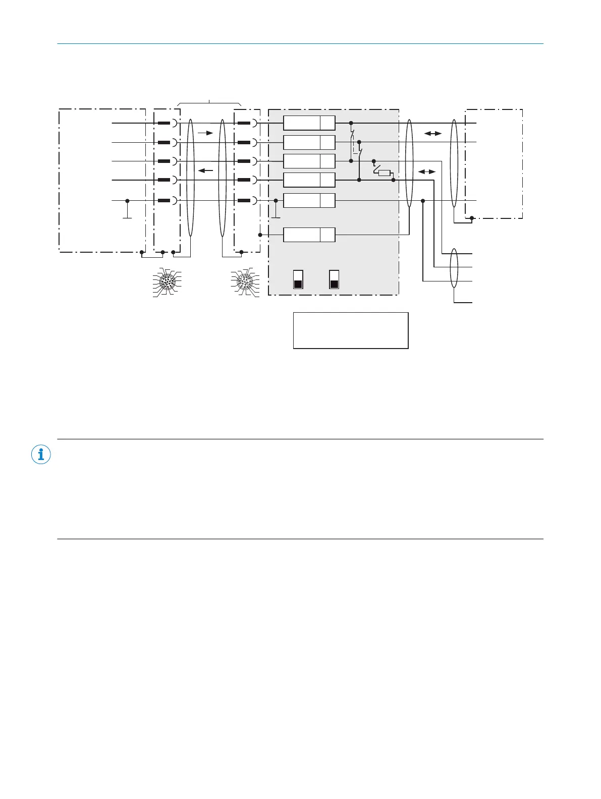
Wire RS-485 data interface of the CLV69x in the CDB650-204 connection module
CLV69x CDB650-204
Host
1
.
.
.
TD+
TD‒
RD+
RD‒
RD+/TD+
RD‒/TD‒
RD+/TD+
To the network:
RD‒/TD‒
GND
GND
GND
Shield
GND
11
12
1
5 5
6
11
12
6
33
T+
43
T‒/TxD
34
R+
44
R‒/RxD
42
GND
6
Shield
RS-485
RS-485
485
422
S6: RS
ON
OFF
S7: Term 485
S6
422
S7
OFF
120Ω
485
S7: Term 485
Set to ON if CLV69x is at the
end of the RS-485 bus cable.
17
16
10
11
12
15
14
6
5
4
13
7
8
9
1
2
3
17
16
10
11
12
15
14
6
5
4
13
7
8
9
1
2
3
M12,
17-pin,
A-coded
For CLV69x-xxx0 (without heating):
no. 6052286 (2m)
no. 6051194 (3m)
no. 6051195 (5m)
For CLV69x-xxx1 (with heating):
no. 6053230 (2m)
no. 6053231 (3m)
no. 6053232 (5m)
1) Dependent on type
Connection cable 1:1
1)
Figure 49: Wire serial host interface RS-485
NOTE
Use of the RS-485 data interface:
•
The relevant interface drivers for the device comply with the standard for RS-422 and RS-485.
•
This operating mode is only permitted if all connected devices use a corresponding RS-485 protocol.
•
Activation of the interface in the device with the SOPAS ET configuration software (point-to-point).
•
This wiring is not permitted in the standard data output/protocol for the device. In case of doubt, contact
SICK Service.
6 ELECTRICAL INSTALLATION
56
O P E R A T I N G I N S T R U C T I O N S | CLV69x 8014396/ZMG8/2017-07-04 | SICK
Subject to change without notice