HostHost
Shield
30 31 32 6
30 31 32 6
30 31 32 6
33
34
43
44
6
30 31 32 6
40 41 42 7
40 41 42 7
CDB650-
204
CDB650-
204
CDB650-
204
CLV69x
CLV69x
CLV69x
(Slave)
(Slave)
(Slave)
GN = 01
CLV69x
(Master)
GN = 63
GN = 02
GN = 03
(max. 32 participants)
Branch line
Switch
ON
OFF
S2 (TermCAN):
Switch
ON
OFF
S2 (TermCAN):
Switch
ON
OFF
S2 (TermCAN):
CAN_H
CAN_L
Shield
GND
CAN_H
CAN_L
Shield
GND
CAN_H
CAN_L
Shield
GND
CAN_H
CAN_L
Shield
GND
GND
GND
GND
RxD
TxD
TD‒
RD‒
RD+
TD+
RS-232RS-422
T‒/TxD
R‒/RxD
T+
R+
CDB650-204
42
Connection
cable 1:1
1)
Connection
cable 1:1
1)
Connection
cable 1:1
1)
Connection
cable 1:1
1)
CAN
CAN
CAN
including CAN
including CAN
including CAN
including CAN
Connection and looping through
of the supply voltage and connection
of the read cycle sensor to e.g.
master neglected here!
Switch
ON
OFF
S2 (TermCAN):
Serial host interface
Ethernet (Host Port)
422
485
S6 (RS):
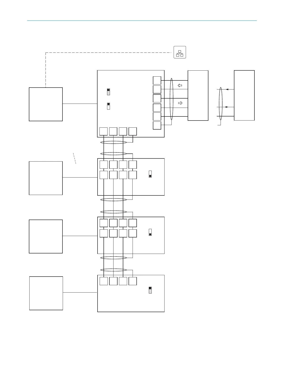
Wire CLV69x in the CDB650-204 connection module for SICK CAN SENSOR network
EthernetEthernet
For CLV69x-xxx0 (without heating):
no. 6052286 (2m)
no. 6051194 (3m)
no. 6051195 (5m)
For CLV69x-xxx1 (with heating):
no. 6053230 (2m)
no. 6053231 (3m)
no. 6053232 (5m)
1) Dependent on type
Figure 50: Wiring the CAN interface
ELECTRICAL INSTALLATION
6
8014396/ZMG8/2017-07-04 | SICK O P E R A T I N G I N S T R U C T I O N S | CLV69x
57
Subject to change without notice