Muting sta‐
t
us
At least one of
the muting sen‐
sor signal inputs
A1, A2, B1, B2 =
1
Input ESPE Output Override
required
Override possible
1 Yes 0 0 No
1 Yes 1 0 No
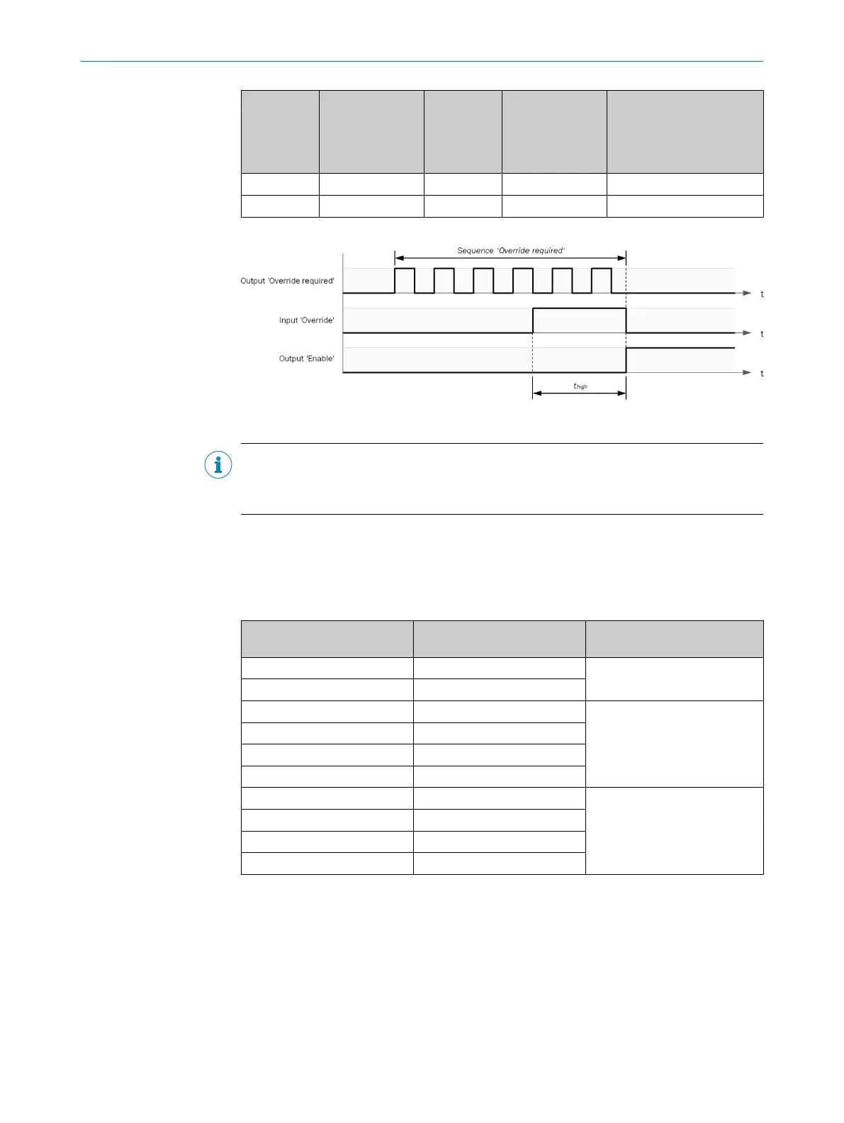
Example sequence for O
verride and Override required:
Figure 50: Sequence/timing diagram for Override and Override required
NOTE
t
hi
gh
≥ 100 ms, but ≤ 3 s.
Otherwise the pulse on the Override input is ignored.
During an override cycle, the Enable out
put is set to 1 in the same way as during a
valid muting sequence. To prevent excessive use of the Override function, the number
of permissible override cycles is limited. The number of permissible override cycles
depends on the value for the total muting time.
Table 120: Number of permissible override cycles
Total muting time Number of permissible over‐
r
ide cycles
Comments
5 s 360 Maximum number of override
cycles = 360
10 s 360
20 s 180 = 60 min/total muting time
30 s 120
1 min 60
5 min 12
15 min 5 Minimum number of override
c
ycles = 5
30 min 5
60 min 5
Disabled (0 = unlimited) 5
The number of override cycles is saved in the function block. This value is incremented
whene
ver the Override required output starts pulsating or whenever the Muting status
output switches to 1. The value is reset to 0 on completion of a valid muting cycle, after
a system reset or after a transition from the Stop status to the Run status.
Once the Override required output has started pulsating at 2 Hz and a subsequent
override signal = 1, muting begins again and the Enable output changes to 1.
If the muting cycle is stopped because of a faulty muting sensor input signal, the
Override required output switches to 1 for the duration of the logic execution time if the
remaining conditions for the Override required output are met. If the faulty muting sensor
7 C
ONFIGURATION
102
O P E R A T I N G I N S T R U C T I O N S | Flexi Compact 8024589/2020-11-10 | SICK
Subject to change without notice