@0.5 A 20 H
1)
Max. –30 V DC, to avoid damaging the output.
Ma
x. –50 V DC, for fast switch-off of inductive loads.
2)
Higher voltages are evaluated as a cross-circuit fault
3)
In the event of a fault (GND line open circuit) and with a load resistance of at least 2.5 kΩ, no more than
the specified leakage current flows on the safety output. For lower load resistances, the leakage current
may be greater however the output voltage will be < 5 V in this case. A downstream device, for example a
relay or a FPLC (fail-safe programmable logic controller) must detect this state as Low.
4)
When activated, the outputs are tested regularly (brief switching to Low). When selecting the downstream
control elements, ensure that the test pulses with the specified parameters do not result in a switch-off,
or deactivate the test pulses on the outputs yourself.
5)
Safety outputs (Q) with test pulses only detect cross-circuits reliably (i.e. already in the switched-on state
and not just after a switch-off) if these values for the supply cable and the connected control element are
not exceeded. Otherwise further measures will be required, for example protected or separate cabling.
(See also EN 60204 Electrical equipment of machines, Part 1: General requirements.)
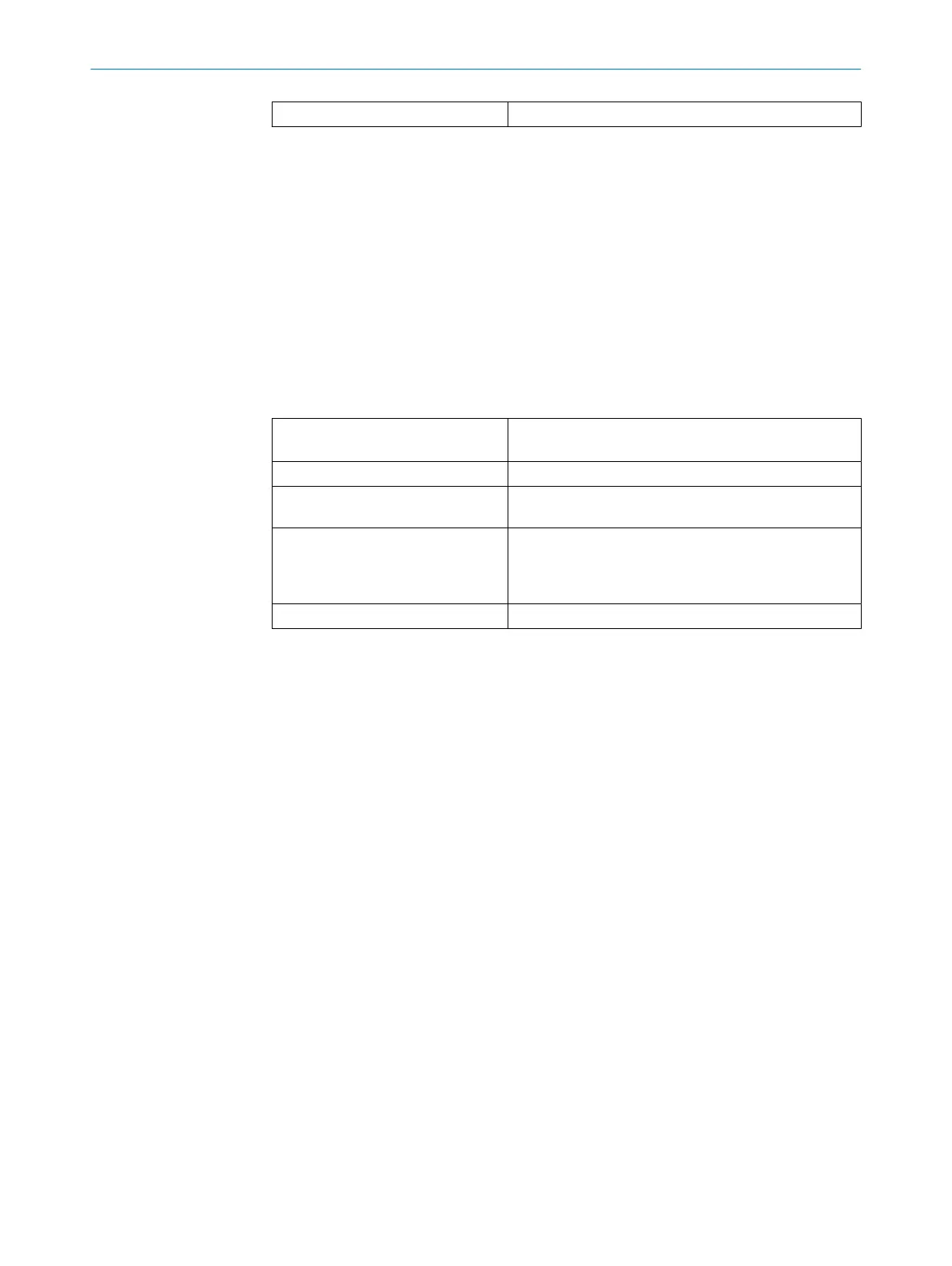
Network interface of the main module
T
able 146: Network interface of the main module
Interface Modbus® TCP
SLMP
Connection type 1 × RJ45 female connector
Transfer rate 10 Mbit/s (10 Base-T) or 100 Mbit/s (100 Base-TX),
aut
osensing
Default settings for addressing IP address: 0.0.0.0
Subnet mask: 0.0.0.0
Default gateway: 0.0.0.0
DHCP: enabled
MAC address Printed on the type label, e.g.: 00:06:77:02:00:A7
13.2 Maximum response time
Safety controller response times
T
he response time of a function depends on the hardware and software configuration
of the safety controller. You need to take all factors into account when calculating the
response time and consider all signal paths separately.
TECHNICAL DATA 13
8024589/2020-11-10 | SICK O P E R A T I N G I N S T R U C T I O N S | Flexi Compact
131
Subject to change without notice