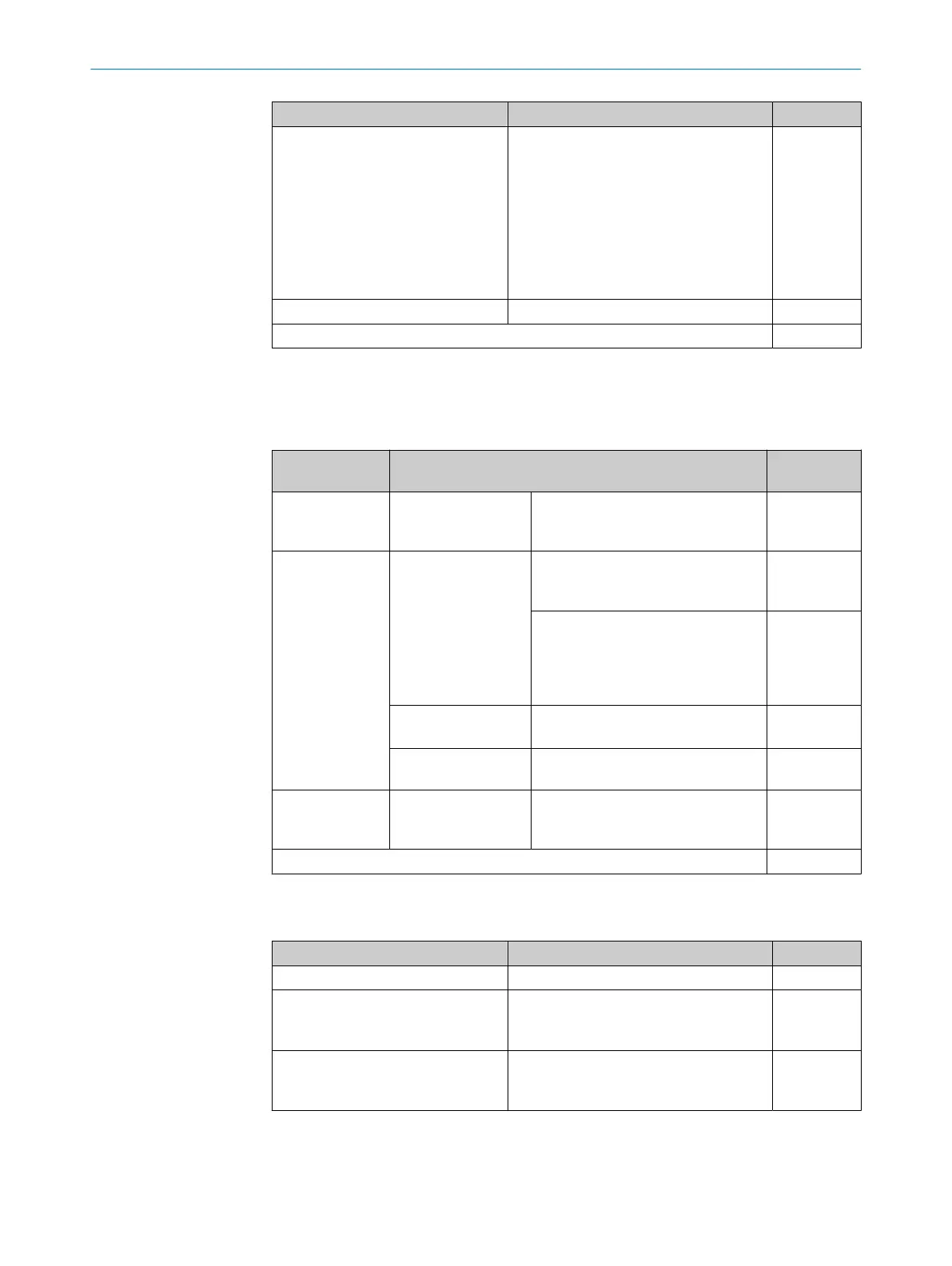
When relevant? Description Value [ms]
When using dual-channel safety out‐
put Q.
For one or both safety outputs:
•
1 ms
A po
tential switch-off delay in the event of
a fault applies to the second safety output
1)
:
•
Without the Increased capacitive loads
allowed option: 5 ms
•
With the Increased capacitive loads
allowed option: 50 ms
1
Fast shut off is used. 0.5 ms –
Total 1
1)
If switch-off occurs, a single safety output (Q) may be switched on rather than switched off for this time in
t
he event of an internal hardware error. An undesired switch-on can also occur in the switched off state
and is limited to 5 ms by a fault switch-off. Ensure, in particular for single-channel safety outputs, that the
resultant pulse does not result in a safety-critical state of the system.
Table 155: Calculating the maximum response time – signal path 1
Components of
t
he calculation
Description Value [ms]
1. Inputs Response time of the
observed input in the
signal path
IN1, IN3, IN4 or IN5
•
see table 153, page 135
3
2. Logic a) Response time
of t
he main module
logic
2 × logic execution time
Take the value from the report in the
configuration software.
8
Delay due to logic application (e.g.
s
witch-on delay or switch-off delay
function block)
Take the value from the report in the
configuration software.
b) Response time of
t
he routing
For OUT3 output to the gateway only
No delay time
0
c) Response time of
t
he fast shut off logic
No delay time 0
3. Outputs Response time of the
observed output in
the signal path
OUT1, OUT2, OUT3, OUT4 or OUT5
•
see table 154, page 135
1
Total 12
Response time of signal path 2
T
able 156: IN1 – Response time of safety capable inputs (I)
When relevant? Description Value [ms]
Always Input processing time 3
ON-OFF debounce filter is configured. Min. debounce filter time
T
ake the value from the report in the con‐
figuration software.
–
Input element is connected to a test
out
put (X).
Max. tolerated test pulse delay
Take the value from the report in the con‐
figuration software.
–
13 TECHNICAL DATA
136
O P E R A T I N G I N S T R U C T I O N S | Flexi Compact 8024589/2020-11-10 | SICK
Subject to change without notice