The function block makes it possible to acknowledge a manual safety stop and subse‐
q
uently restart the application.
Important information
WARNING
U
ndesired reset following short-circuit to High
The dangerous state may not be stopped or not be stopped in a timely manner in the
event of non-compliance.
b
Make sure the signal line is laid with protection (to prevent a cross-circuit with
other signal lines).
b
No short-circuit detection, i.e., no referencing to test outputs.
Principle of operation
T
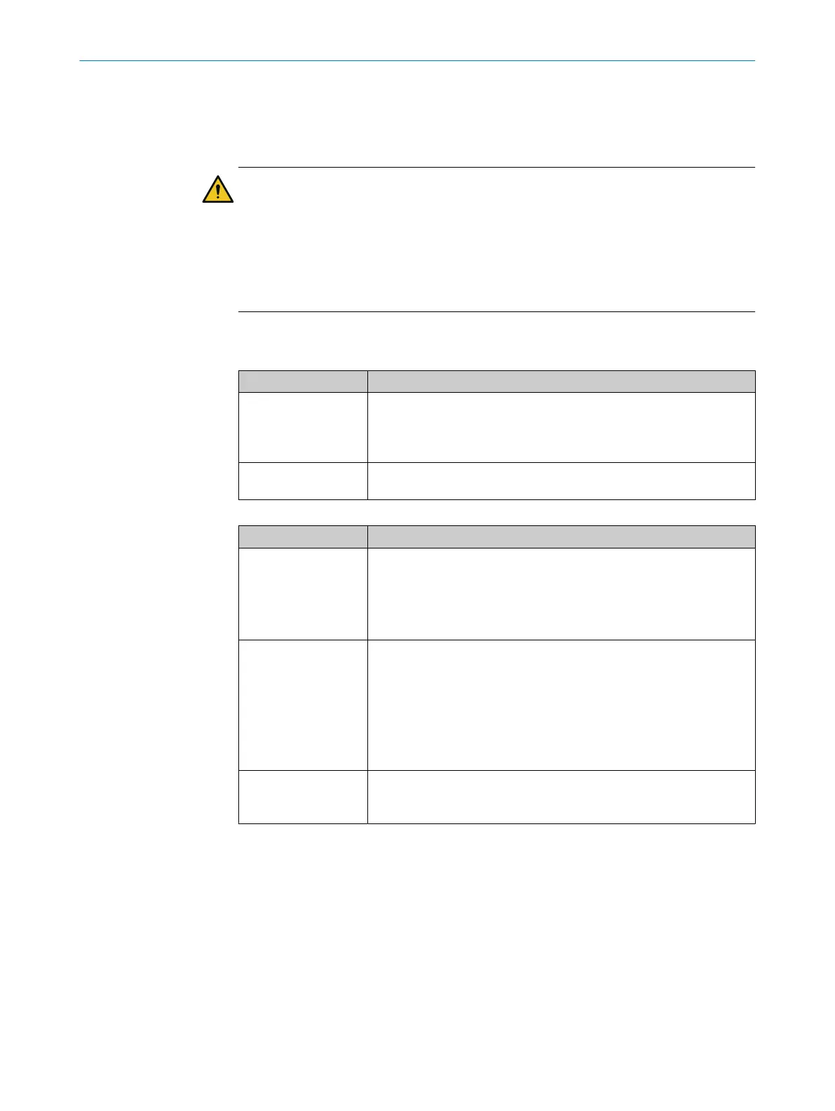
able 93: Inputs
Input Description
Reset Data type: Boolean
F
or connecting a reset command switch.
A valid reset sequence comprises the signal sequence 0–1–0.
Pulse duration: 100 ms … 30 s, at least 2 × logic execution time
Release Data type: Boolean
See Enable out
put.
Table 94: Outputs
Output Description
Enable Data type: Boolean
R
esets the safety device.
•
When the Release input = 1 and the function block detects a valid
reset pulse on the Reset input, the Enable output switches to 1.
•
The Release output remains = 1 as long as the Enable input = 1.
Reset required Data type: Boolean
T
he output pulsates at 1 Hz to indicate that the function block is
expecting a valid reset pulse at the Reset input so that the Enable output
can switch to 1.
When the Release input = 1 and the function block detects a rising
signal edge at the Reset input, the Ready for reset output switches perma‐
nently to 1.
You can use this output to control an indicator lamp.
Ready for reset Data type: Boolean
T
he output switches to 1 when a valid pulse at the Reset input leads to
activation of the Enable output.
CONFIGURATION 7
8024589/2020-11-10 | SICK O P E R A T I N G I N S T R U C T I O N S | Flexi Compact
85
Subject to change without notice