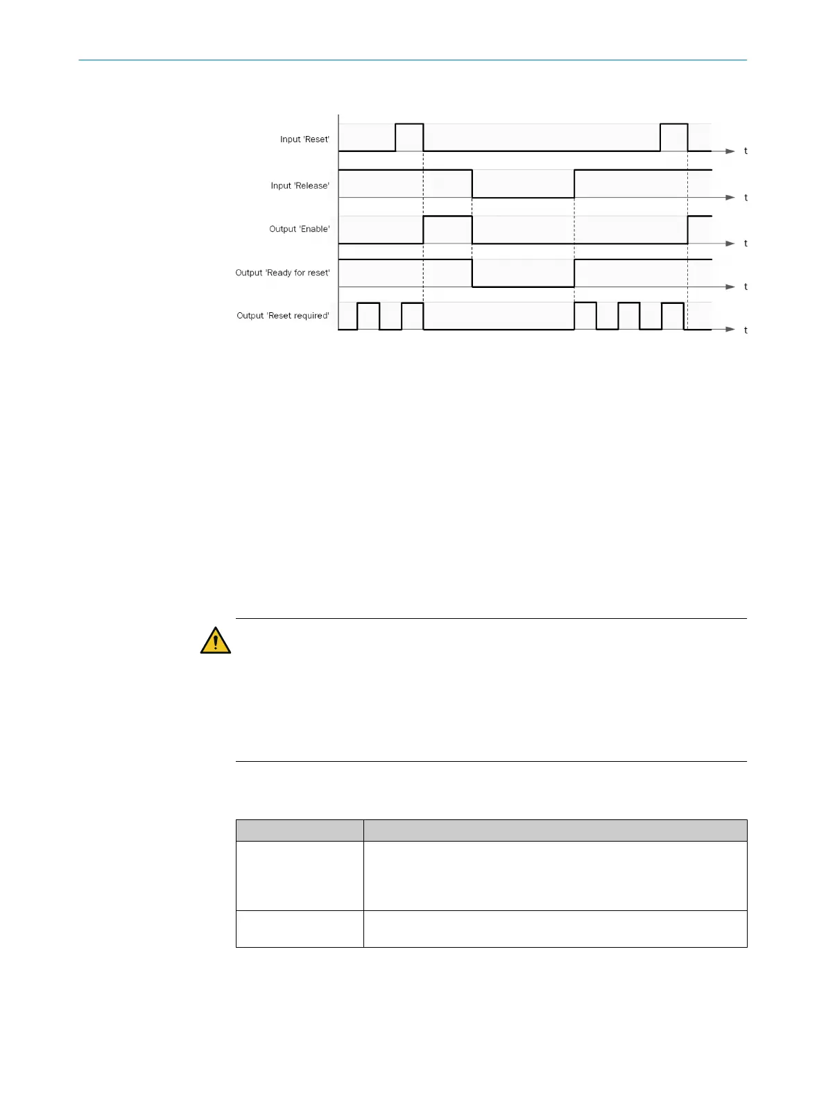
Sequence/timing diagram
Figure 40: Sequence/timing diagram
Complementary information
T
o evaluate the minimum length of the reset pulse (here: 100 ms), the reset signal
must be sampled twice after a 0→1 transition is detected. The required minimum
length of the reset signal is therefore extended by one logic execution time.
7.6.2.6.2 Restart V1 (Restart)
Overview
Y
ou can use this function block to implement a restart function.
The function block makes it possible to acknowledge a manual safety stop and subse‐
quently restart the application.
Important information
WARNING
U
ndesired reset following short-circuit to High
The dangerous state may not be stopped or not be stopped in a timely manner in the
event of non-compliance.
b
Make sure the signal line is laid with protection (to prevent a cross-circuit with
other signal lines).
b
No short-circuit detection, i.e., no referencing to test outputs.
Principle of operation
T
able 95: Inputs
Input Description
Restart Data type: Boolean
F
or connecting a restart command switch.
A valid restart sequence comprises the signal sequence 0–1–0.
Pulse duration: 100 ms … 30 s, at least 2 × logic execution time
Release Data type: Boolean
See Enable out
put.
7 CONFIGURATION
86
O P E R A T I N G I N S T R U C T I O N S | Flexi Compact 8024589/2020-11-10 | SICK
Subject to change without notice