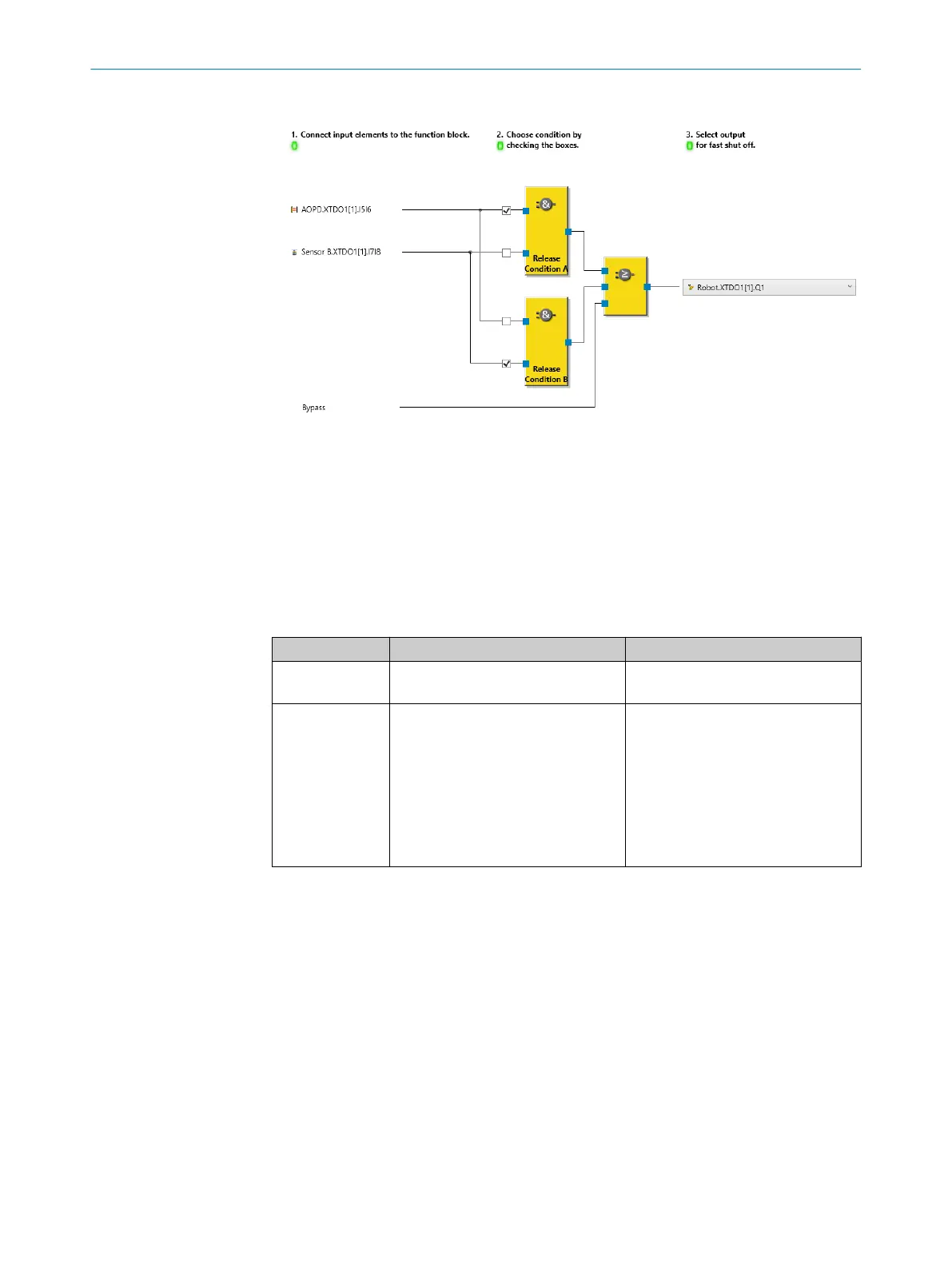
Figure 39: Example of Fast shut off V1 internal logic for alternative enable conditions
Examples for the use of bypass
•
Oper
ation of a machine or system in Setup mode (bypass is activated, for example,
using an enabling pushbutton)
•
Muting during the upwards movement of a press (bypass is activated with the help
of a press signal)
Response time
Table 92: Response times
Input Response time for switch-off Response time for switch-on
Input 1 … Input 8 Fast shut off response time No effect on the response time →
N
ormal response time
Bypass No effect on the response time →
Normal response time
Normal response time + switch-on
delay of 3 logic cycles
The switch-on delay compensates for
the processing time of the logic. To
bypass fast shut off, the Bypass input
must be set to 1 at least 3 logic
cycles in advance in the logic before
the input signal changes to 0 on the
physical input.
Complementary information
•
T
he value of the connected output in the online monitor of the logic may deviate
from the actual value of the physical output.
Further topics
•
"Maximum response time", page 131
7.6.2.6 Function blocks for applications
7.6.2.6.1 Reset V1
Overview
Y
ou can use this function block to implement a reset function.
7 C
ONFIGURATION
84
O P E R A T I N G I N S T R U C T I O N S | Flexi Compact 8024589/2020-11-10 | SICK
Subject to change without notice