Installation
FLOWSIC100 Flare · Addendum to Operating Instructions · 8025365/V1-0/2020-05 · © SICK Engineering GmbH 49
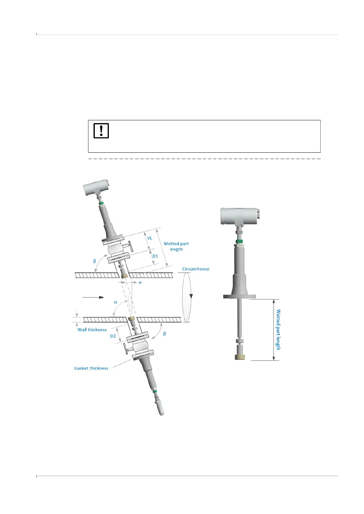
– Wall thickness w
– Gasket thickness S
– Nozzle length D1 or D2
– For installation with ball valve: Length of ball valve VL
– Angle β: For cross-duct versions, enter the nominal nozzle angle (e.g. 75°, 60°,
45°). For the probe version, measure the installation angle and enter the exact
value (maximum tolerance for the measurement of the installation angle: ±0.3°).
Wetted part length wL and the geometric installation parameters are calculated.
Fig. 27 Installation of F1F-S, F1F-M, F1F-H (cross-duct versions)
NOTICE:
The geometric installation parameters in the area "Result: Parameter for pro-
gram configuration" and the wall thickness are required for the parameteriza-
tion of the measuring system during commissioning.
 Loading...


