5 Mounting
5.1 Mounting instructions
•
Observe the technical data.
•
Protect the sensor from direct sunlight.
•
To prevent condensation, avoid exposing the device to rapid changes in tempera‐
ture.
•
The mounting site has to be designed for the weight of the device.
•
Avoid having shiny or reflective surfaces in the scanning range, e.g., stainless
steel, aluminum, glass, reflectors, or surfaces with these types of coatings.
•
Protect the device from moisture, contamination, and damage.
•
Make sure that the status indicator is clearly visible.
•
Do not subject the device to excessive shock or vibrations. In systems subjected to
heavy vibrations, secure the fixing screws with screw-locking devices.
5.2 Mounting the device
NOTE
So that precipitation (rain, fog, etc.) can drain away more effectively and/or to reduce
dustfall, mount the device upside down (optics cover down) and with the connectors
facing downward.
1. Mount the device in a suitably prepared bracket using the fixing holes provided
(see "Mechanics/Electronics", page 40). Mounting brackets are available as
accessories, "Accessories", page 43.
2. Make the electrical connection. Attach and tighten the tension-free cable, see
"Overview of the installation steps", page 29.
3. Align the vertical center line of the field of view of the device with the center of the
area to be monitored. The marking on the upper side of the optics cover serves as
a bearing alignment aid.
4. Switch on the supply voltage.
5. Perform a fine adjustment using a test target and, if necessary, use the alignment
aid.
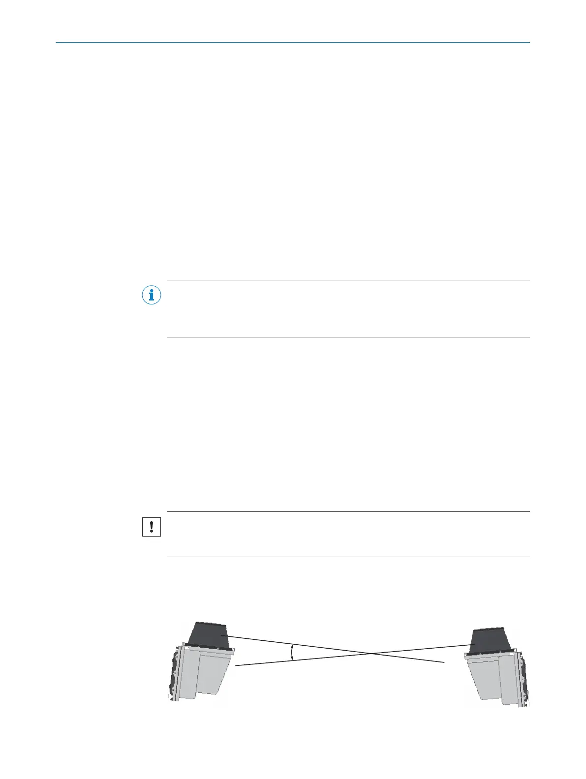
5.3 Mounting multiple devices
NOTICE RISK OF INTERFERENCE FROM OTHER DEVICES!
Radiation sources with a wavelength of 905nm can cause interference if they affect
the device directly.
The device has been designed to minimize the probability of mutual interference,
including between different LiDAR sensors. To rule out even the slightest effects on the
measurement accuracy, the devices should be arranged such the laser beams are not
received by another device.
Figure 16: Arrangement for 2 devices
MOUNTING 5
8016506/1G07/2020-11-08 | SICK O P E R A T I N G I N S T R U C T I O N S | LD-LRS
25
Subject to change without notice