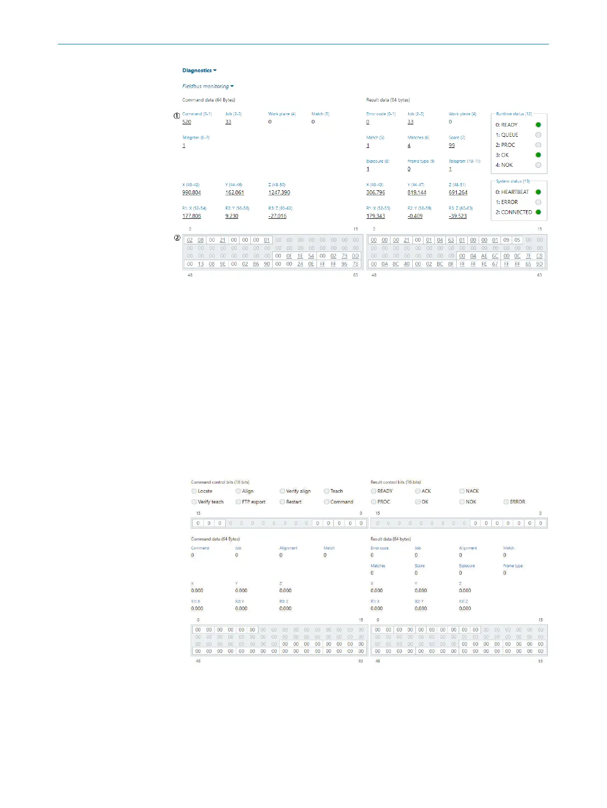
Figure 27: Fieldbus monitor using telegram ID
1
Data fields
2
64-byte registers
Fieldbus monitoring using control bits
This applies when the Protocol version "Using control bits" is selected in "Fieldbus config‐
uration", page 55.
•
The left part of the monitor represents the commands sent to the device.
•
The right part of the monitor represents the results sent from the device.
•
The two 16-bit registers represent control bits.
•
The control lights next to the control names are visualizations of the control bits.
•
The two 64-byte registers represent data fields.
•
The data fields are interpreted and presented between the registers.
•
Mouse over the registers to see the parameter used for that specific bit or byte.
Figure 28: Fieldbus monitor using control bits
1
Control lights
2
16-bit registers
3
Data fields
4
64-byte registers
OPERATION 7
8020736/1K3Z/2023-06 | SICK O P E R A T I N G I N S T R U C T I O N S | PLOC2D 4.1
57
Subject to change without notice