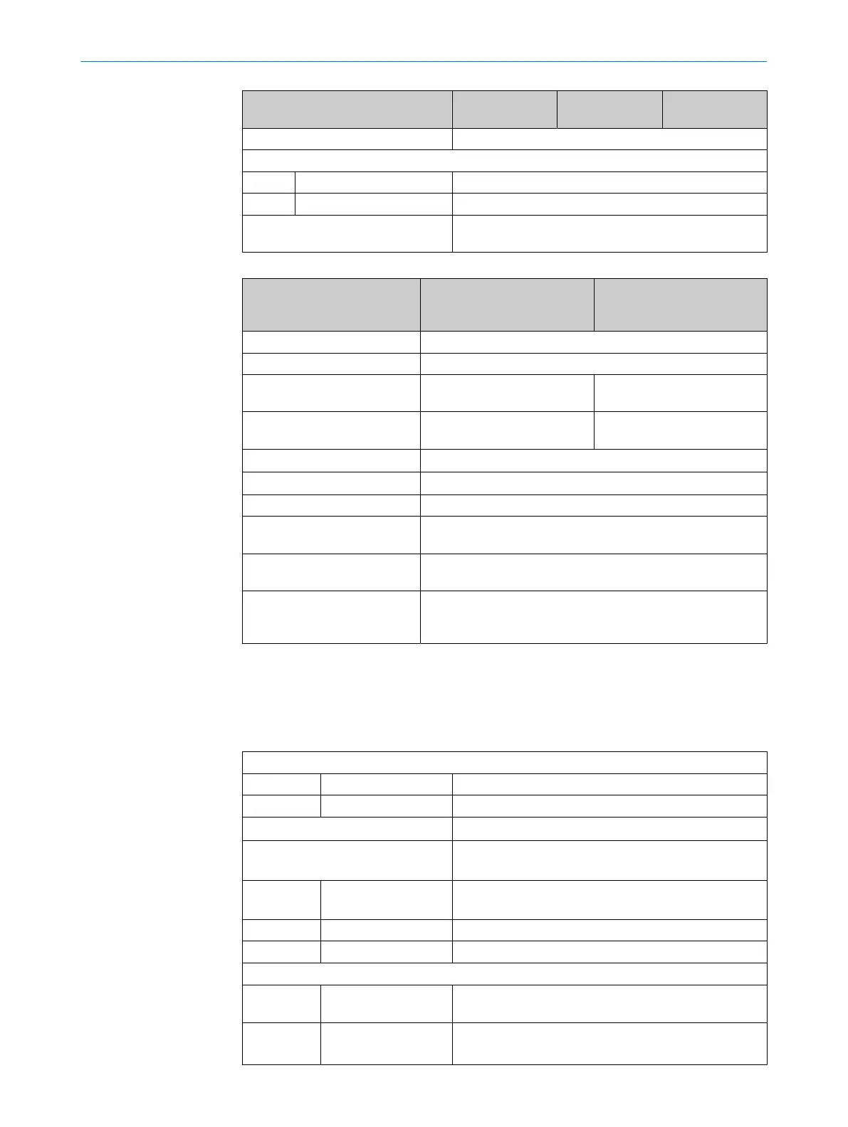
Type SLGxxx-xxxxAxxxx SLGxxx-
xxxxCxxxxxx
SLGxxx-
xxxxExxxxxx
Number of beams 2 - 240 beams
Light source
Type of light Infrared light
Wavelength 850 nm
Parameterization interface Pin 2 / MF (teach-in)
IO-Link
Table 22: Time response
Type SLGxxS-xxxxxRxxA00
SLGxxS-xxxxxRxxD0x
SLGxxS-xxxxxRxxD1x
SLGxxS-xxxxxRxxD2x
SLGxxS-xxxxxRxxD3x
SLGxxS-xxxxxRxxD4x
Initialization time 0,4 s ... 2 s
1)
Teach-in time 0,75 ... 24 s
1)
Scan time (parallel beam) 0,041 ms * number of beams
+ 0,5 ms
2)
0,041 ms * number of beams
+ 0,75 ms
2)
Scan time (cross beam) 2 * (0,041 ms * number of
beams + 0,5 ms)
3)
2 * (0,041 ms * number of
beams + 0,75 ms)
3)
Repeatability (parallel beam) scanning time
Repeatability (cross beam) 1.5 * scan time
Minimum dwell time 2 * scan time
Max. response time (parallel
beam)
3 * scan time + 0,015 ms * number of beams - 0,25 ms
Max. response time (cross
beam)
2.5 * scan time + 0,048 ms * number of beams + 0,6 ms
Offset after loss of optical syn‐
chronization
≤ 10 beams: 6 * scan time
≤ 40 beams: 4 * scan time
>40 beams: 2 * scan time
1)
Depending on the installed working distance / number of beams / cross-beam setting
2)
Minimum scan time (parallel beam) = 1 ms
3)
Minimum scan time (cross beam) = 2 ms
Electrical data
Table 23: Electrical data
Power consumption of sender @ 24 V
Sender ≤ 0,075 mA x number of beams + 35 mA
Receiver ≤ 0,6 mA x number of beams + 39 mA
1)
Supply voltage (U
B
) DC 18 ... 30 V
Switching output/inputs 2 outputs: Q
L1
, Q
L2
(MF)
1 Input: MF
Output current per
switching output l
max
100 mA
Capacitive output load 100 nF max.
Inductive output load 1 H max.
Logic level
Input: HIGH > 15 V
LOW < 5 V
Output: HIGH
VS
>U
B
- 3 V
LOW
VS
< 3 V
11 TECHNICAL DATA
52
O P E R A T I N G I N S T R U C T I O N S | SLG-2 8026014/2021-06-10 | SICK
Subject to change without notice