Tabella 4: DC
WTB4Sx- xx112xx0Zxx xx111xx0Zxx xx312xx0Zxx xx311xx0Zxx
1 = BN + (L+)
2 = WH Q
Q
nessuna funzione
3 = BU - (M)
4 = BK
Q
Q
Q
Q
Tabella 5: DC
WTB4Sx- xxXXXxx0Zxx
Push-pull 311 312
PNP A11 A12
NPN E11 E12
1 = BN + (L+)
3 = BU - (M)
4 = BK Q
Q
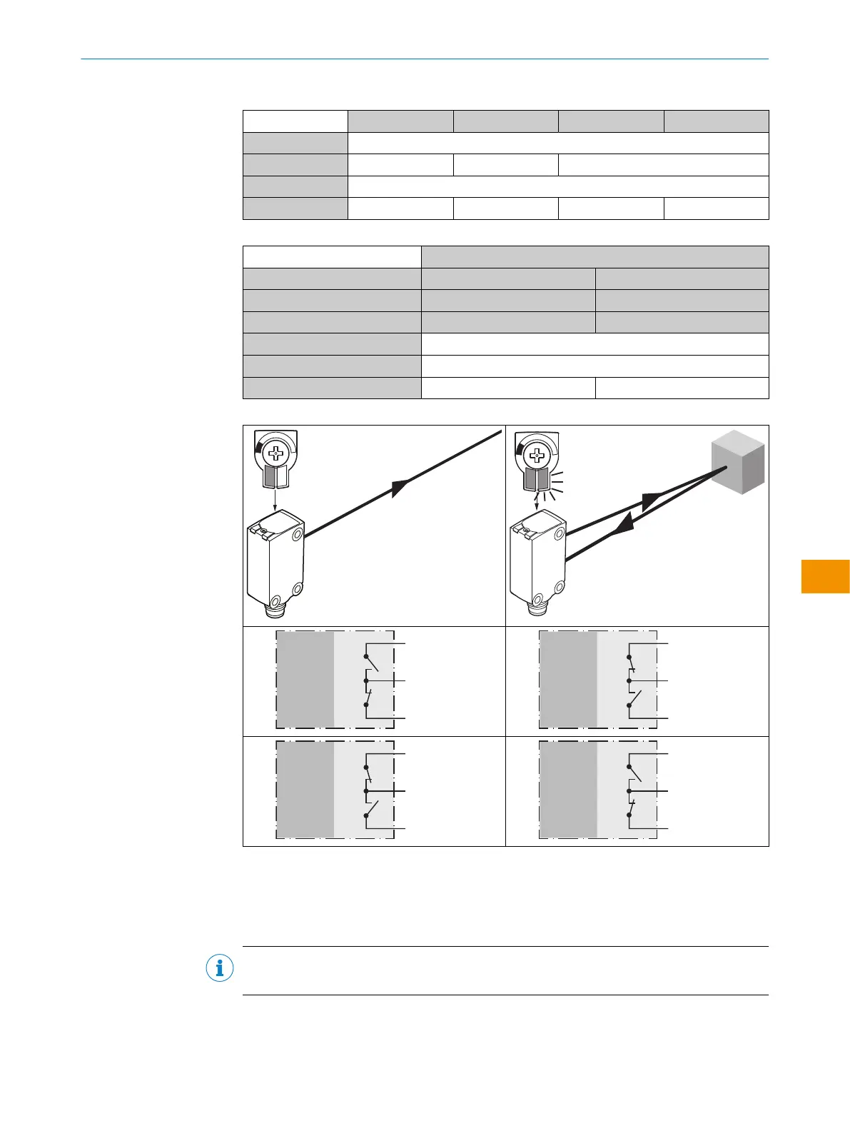
Tabella 6: Push-pull, PNP, NPN
Push-pull
PNP
NPN
+ (L+)
Q ≤ 100 mA
‒ (M)
Push-pull
PNP
NPN
+ (L+)
Q ≤ 100 mA
‒ (M)
Push-pull
PNP
NPN
+ (L+)
Q ≤ 100 mA
‒ (M)
Push-pull
PNP
NPN
+ (L+)
Q ≤ 100 mA
‒ (M)
5.4 Integrazione del sensore in modalità IO-Link
Per utilizzare il prodotto in modalità IO-Link, è necessario collegarlo a un IO-Link Master
adeguato. Questo viene utilizzato per un'ulteriore integrazione nel sistema di controllo.
INDICAZIONE
Lunghezza del cavo tra l’IO-Link Master e l’IO-Link Device: massimo 20m.
I dettagli sull'integrazione sono riportati nella descrizione dettagliata di IO-Link: Infor‐
mazioni tecniche: Sensori fotoelettrici, SICK Smart Sensors/IO-Link.
ISTRUZIONI PER L’USO
8028211/2023/10/20 | SICK I S T R U Z I O N I P E R L ’ U S O | WTB4S
113
Contenuti soggetti a modifiche senza preavviso
it