Figure 1: SICK product ID
3.2 Control and display elements
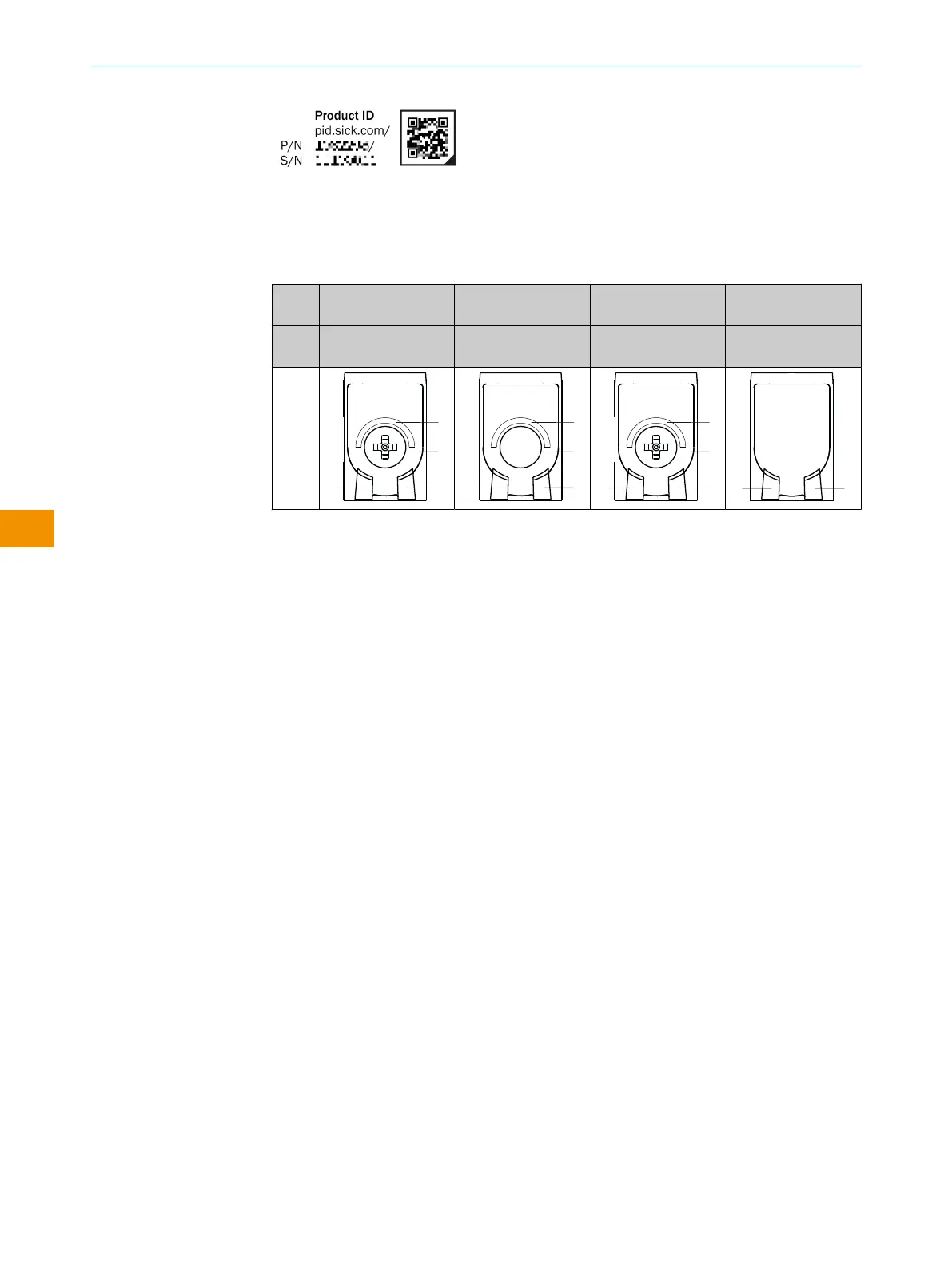
Table 1: Control and display elements
WTB4
Sx-
xxxxxx20 xxxxxx30 xxxxxx10 xxxxxxA0
Teach-Turn adjust‐
ment
Teach-in button Potentiometer Preset default - no
possibility of setting
1
Green LED: supply voltage active
2
Yellow LED: status of received light beam
3
Press-turn element / Potentiometer / Teach-Button: adjusting the sensing range
4
BluePilot blue: sensing range display
3.3 IO-Link communication interface
The product comes with the IO-Link communication interface.
IO-Link communication is a master-device communication system.
The product can be operated in standard I/O mode (SIO) or IO-Link mode (IOL). All
automation functions and other parameter settings are effective in IO-Link mode and in
standard I/O mode.
The following functions are supported via the standard IO-Link communication inter‐
face:
•
Flexible sensor settings
•
Digital transmission of sensor signals to the IO-Link Master
•
Visualization and configuration of the sensor
•
Diagnostics /condition monitoring
•
Device identification
•
Easy device replacement
•
Events
A detailed description of the configurable functions and associated indices can be
found in the “IO-Link description” technical Information: Technical Information: Photo‐
electric sensors, SICK Smart Sensors / IO-Link.
3.3.1 Documentation and accessories
Accessory components and additional information are available for integrating and
configuring the IO-Link device. You can find documentation and software, accessories
and links using the SICK ProductID, see "Product identification via the SICK product ID",
page 31.
OPERATING INSTRUCTIONS
32
O P E R A T I N G I N S T R U C T I O N S | WTB4S 8028211/2023/10/20 | SICK
Subject to change without notice
en