Device Connections
Position of the Connections
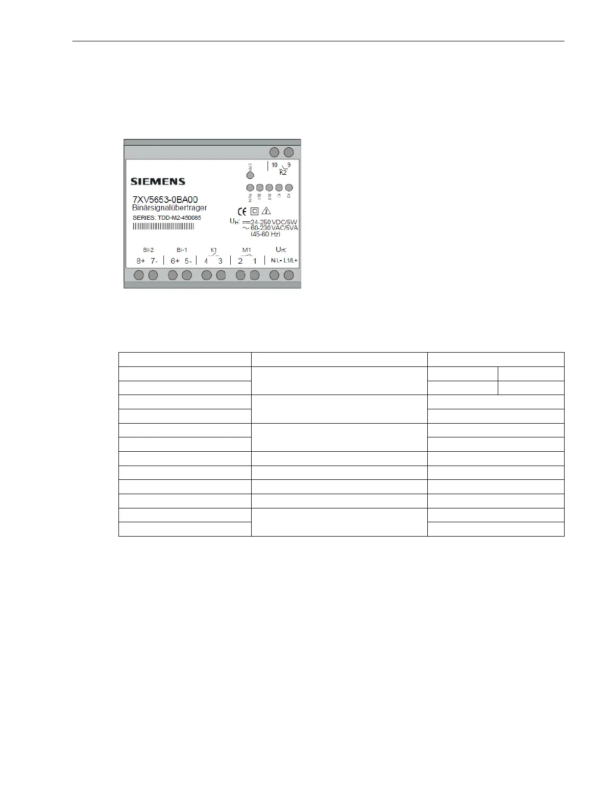
[scbst7xv5653_front, 1, --_--]
Figure 2-1 Front View of the Binary Signal Transmitter
Table 2-1 Terminal Assignment
Connection Meaning Abbreviation
A/L+
Auxiliary voltage V
aux
DC: L+ AC: A
N/L- DC: L- AC: N
1
Alarm relay contact M1
1 (break contact)
2 2 (break contact)
3
Command relay K1
3 (make contact)
4 4 (make contact)
5- Binary input 1- BI-1-
6+ Binary input 1+ BI-1+
7- Binary input 2- BI-2-
8+ Binary input 2+ BI-2+
9
Command relay K2
9 (make contact)
10 10 (make contact)
2.2
2.2.1
Device Structure
2.2 Device Connections
Accessories, Binary signal transmitter 2-channel, Manual 15
C53000-G9050-C607-1, Edition 09.2019
 Loading...