RS232 Interface and DIP Switches
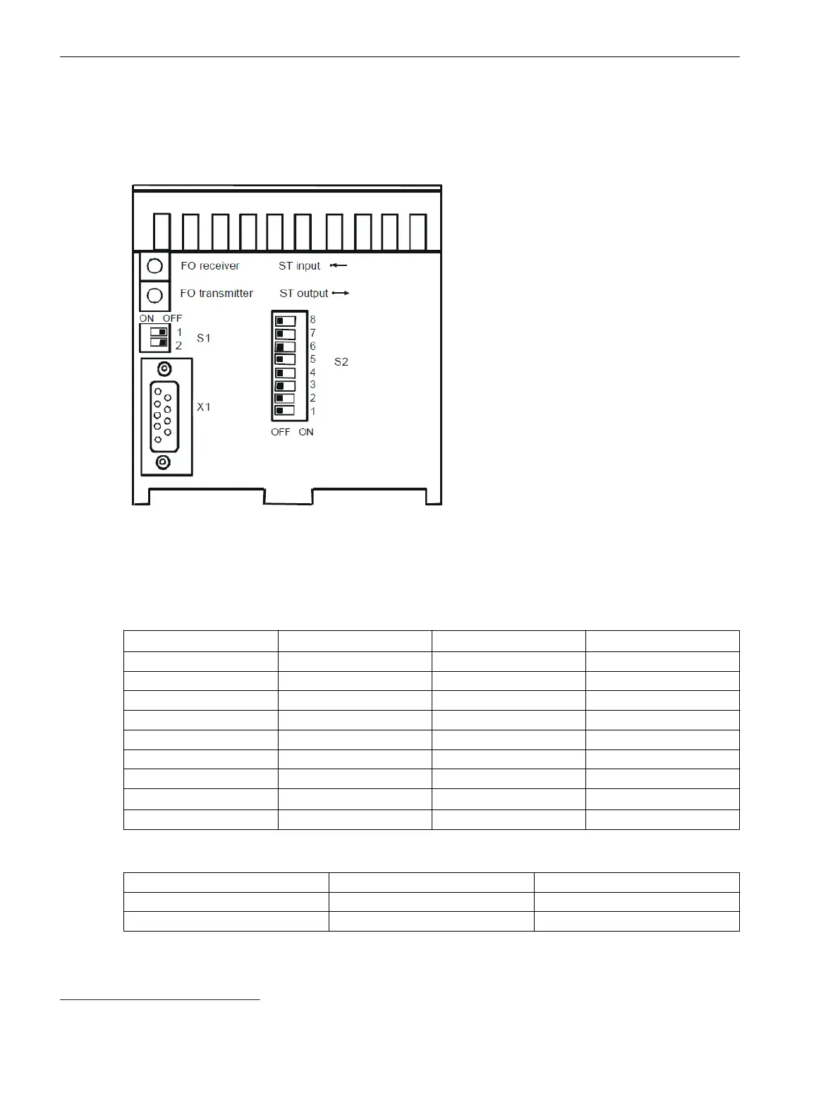
The following figure shows the location of the RS232 interface and the DIP switches from the front. The DIP
switches S1 and S2 can be toggled from the outside.
[scswitchpos7xv5653, 1, en_US]
Figure 2-2
Location of the RS232 Interface and DIP Switches
RS232 Interface X1
Table 2-2
Connector Assignment of the RS232 Interface X1, 9-Pin D-Sub Socket
Pin Description Abbreviation
Direction as DTE
4
1 – – Not assigned
2 Receive data RxD On
3 Transmit data TxD Off
4 – – Not assigned
5 Signal ground GND –
6 – – –
7 Signal ground GND –
8
5
Toggle Toggle On
9 – – –
Table 2-3 Properties of X1, Pin 8:
Toggle Meaning Comments
Not connected Fiber-Optic connection active Pin 8 open
Toggle = ground RS232 connection active Jumper pin 8 - pin 7
2.3
4
Data Terminal Equipment
5
Properties, see Table 2-3
Device Structure
2.3 RS232 Interface and DIP Switches
16 Accessories, Binary signal transmitter 2-channel, Manual
C53000-G9050-C607-1, Edition 09.2019
 Loading...