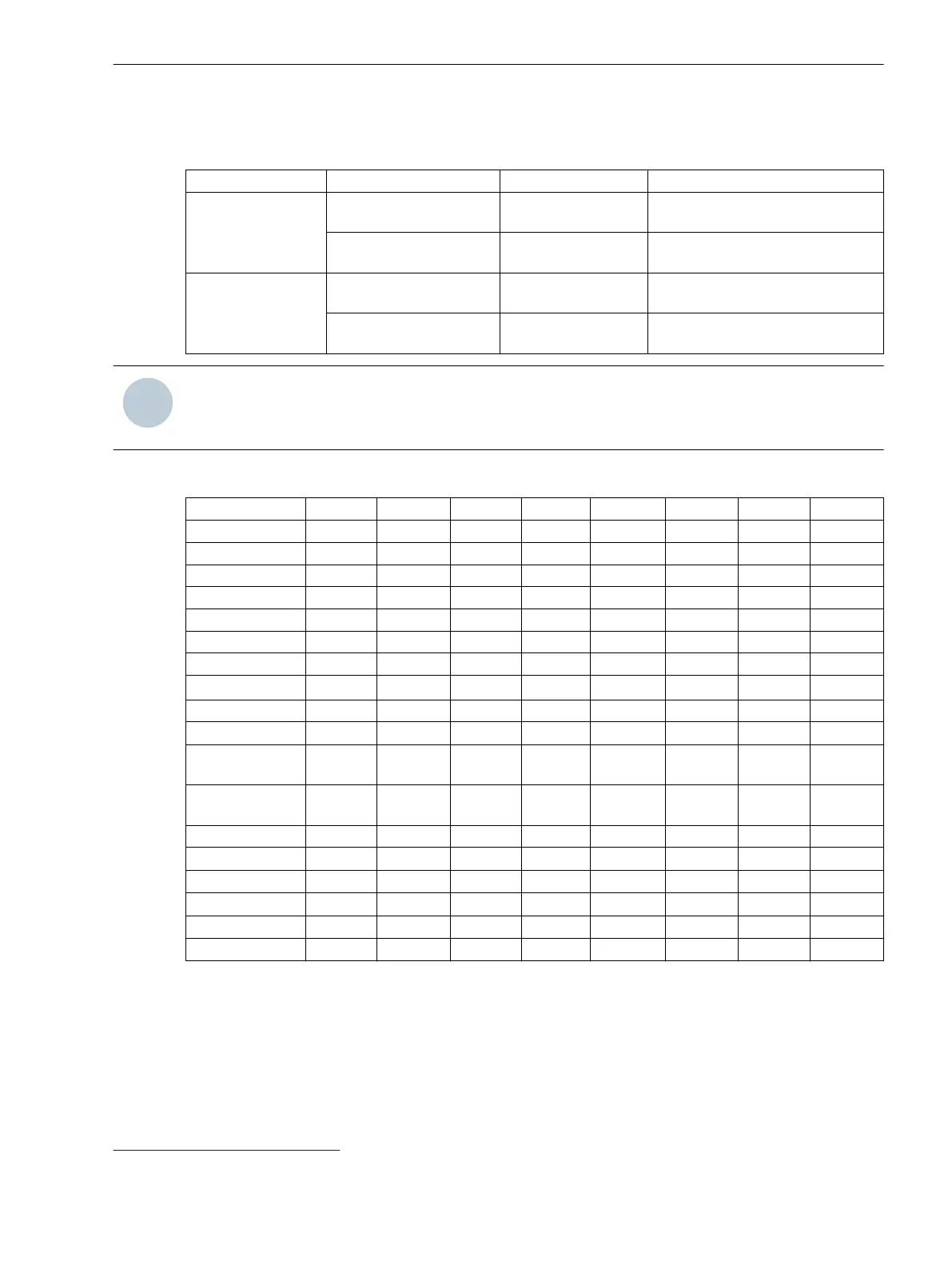
DIP S1 and DIP S2 Switch Positions
Table 2-4 Settings of the DIP Switch S1, 2 Switches
Switch Setting Default Setting Meaning
DIP S1-1 Open = OFF X Light idle state off; receiving on
optical fiber
Closed = ON – Light idle state on; receiving on
optical fiber
DIP S1-2 Open = OFF X Light idle state off; transmitting on
optical fiber
Closed = ON – Light idle state on; transmitting on
optical fiber
NOTE
The baud rate (switch positions DIP S2-1 to DIP S2-3) is checked once after the binary-signal transmitter is
powered. During active test mode, the baud rate is checked and reset continuously.
Table 2-5 Settings of the DIP Switch S2, 8 Switches
Meaning DIP S2-1 DIP S2-2 DIP S2-3 DIP S2-4 DIP S2-5 DIP S2-6 DIP S2-7 DIP S2-8
1200 baud ON ON ON – – – – –
2400 baud OFF ON ON – – – – –
4800 baud ON OFF ON – – – – –
9600 baud OFF OFF ON – – – – –
19 200 baud ON ON OFF – – – – –
38 400 baud OFF ON OFF – – – – –
57 600 baud ON OFF OFF – – – – –
115 200 baud
OFF
6
OFF
6
OFF
6
– – – – –
8E1 – – – ON – – – –
8N1 – – –
OFF
6
– – – –
Disable signal
outputs
– – – – ON – – –
Enable signal
outputs
– – – –
OFF
6
– – –
Test mode on – – – – – ON – –
Test mode off – – – – –
OFF
6
– –
Transmitter only – – – – – – ON –
Transmit/receive – – – – – –
OFF
6
–
Boot loader on – – – – – – – ON
Boot loader off – – – – – – –
OFF
6
where:
8E1:
8 data bits, even parity, 1 stop bit
8N1: 8 data bits, no parity, 1 stop bit
6
Factory setting
Device Structure
2.3 RS232 Interface and DIP Switches
Accessories, Binary signal transmitter 2-channel, Manual 17
C53000-G9050-C607-1, Edition 09.2019
 Loading...