Electrical Connection
General Information
The following chapters describe the connection of all data and power-supply lines necessary for safe opera-
tion. During electrical installation, observe the regulations for the setup of high-voltage systems.
NOTE
If using stranded wires, bootlace ferrules must be used.
Auxiliary-Voltage Connection V
aux
The auxiliary voltage of the device is to be provided with an external disconnecting device (switch) to discon-
nect the power supply and with protection equipment (fuse, 2 A, time delay or 4 A, time delay). The external
disconnecting device must be marked. It is also possible for a miniature circuit breaker to perform both func-
tions.
The auxiliary-voltage connection V
aux
is routed via 2 terminals (N/L-; L1/L+). The large auxiliary voltage range
of DC 24 V to 250 V and AC 60 V to 230 V allows the connection (without a switchover) to all common station
batteries or alternating voltage networks.
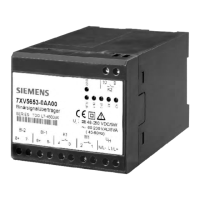
One LED display for the operating voltage (green LED: RUN) is provided in the enclosure cover.
Use the following cable properties:
•
The conductor cross-section (1-wire conductor or stranded wire) is 0.5 mm
2
to 2.5 mm
2
.
•
Recommended stripping length: 5 mm.
Fault-Signaling Contact, Command Relay, and Binary Inputs
The fault-signaling connection is equipped with an isolated contact that is automatically closed by the device
in case of an error. A power-supply outage is considered to be an error. The fault-signaling contact is
connected to the device via the M1 terminals.
The assignments of the binary inputs (BI-1/2) and of the command relay (K1/2) are also printed on the front of
the device.
Terminals:
Fault-signaling
connection, binary
inputs, command
relay:
Max. 2.5 mm
2
(AWG 14 to AWG 24)
Stripped length 3 mm to 5 mm
Conductor cross-
section:
0.14 mm
2
to 1.5 mm
2
(AWG 16 to AWG 22)
Fiber-Optic Connections Tx, Rx
NOTE
Use only optical fibers configured as per regulations.
4.2
4.2.1
4.2.2
4.2.3
4.2.4
Assembly and Commissioning
4.2 Electrical Connection
Accessories, Binary signal transmitter 2-channel, Manual 33
C53000-G9050-C607-1, Edition 09.2019
 Loading...
