Binary-Signal Transmission Using the LOGEM928 and LGH28.8D
Dedicated Line Modems
The following describes the settings for binary-signal transmission via the dedicated line modems LOGEM928
and LGH28.8D (firmware 4.13) with 2-wire operation.
Settings of the DIP Switches on the Dedicated Line Modem
²
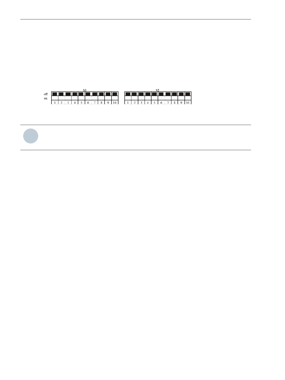
Before initializing the dedicated line modem, set the DIP switches on the modem as follows:
[scbstdipmodem, 1, --_--]
Figure 3-5 DIP-Switch Setting
NOTE
The modem is switched off during the setting process. The changed settings are adopted only when the
dedicated line modem is switched on.
Initializing the Modem
²
Connect the PC to the modem using a modem cable.
²
Initialize the modem before commissioning. To do this, use a terminal program such as Hyperterminal.
²
Before initializing the modem, perform a reset. For this, press and hold the key when connecting the
auxiliary voltage until the LED A/O flashes.
²
Transmit the following AT commands via the Hyperterminal to the modem A and repeat the process for
modem B:
For 19 200 Bd:
Modem A: AT &F0 \N0 \Q0 &D0 F40 S51=11 %C0 S20=0 &L2 E0 Q1 &W↵
Modem B: AT &F0 \N0 \Q0 &D0 F40 S51=11 %C0 S20=0 &L3 E0 Q1 &W↵
→ Each modem responds with OK via the terminal.
Table 3-1
Explanation of the AT Commands:
Command Meaning
&F0 = Load factory settings
\N0 = Normal mode (no data compression, no error correction)
\Q0 = No flow control
&D0 = Control line S1/108 is ignored
F40 = Transmission scheme V.34
S51=11 = Fixed baud rate to terminal device (RS232 interface)
%C0 = No data compression
S20=0 = Ignore characters in command phase
&L2 = Calling modem
&L3 = Receiving modem
E0 = No echo
Q1 = Deactivate result codes
&W = Write settings in EEPROM
3.2
Application Examples
3.2 Binary-Signal Transmission Using the LOGEM928 and LGH28.8D Dedicated Line Modems
26 Accessories, Binary signal transmitter 2-channel, Manual
C53000-G9050-C607-1, Edition 09.2019
 Loading...