4
21 |
Building Technologies
4.2.1 Defining controls
Connections for controls are available on the following components / control
panels:
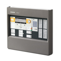
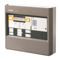
● Fire control panels FC721
● Input module FDCI221
● Input module FDCI222
● Input/output module FDCIO222
● Input/output module FDCIO222
● Input/output module FDCIO223
● Input/output module FDCIO224
● Addressable alarm indicator FDCAI224
The table below shows the control outputs available for the different hardware
modules.
FC721 FDCI221 FDCI222 FDCIO221 FDCIO223
FDCIO222/
FDCIO224
RT alarm (relay) 1 – – – – –
Alarm output (monitored) 1 – – – – –
RT fault (relay) 1 – – – – –
Alarm output (monitored) 1 – – – – –
Monitored horn lines 1 – – 1 2 –
Monitored contact inputs – 1 4 1 – 4
Non-monitored control
outputs/contact inputs
4 freely
configurable
I/Os
– – – – 4 outputs
Table 1: Control outputs in the fire detection system
Notes
● The outputs can be used for any controls. Any events, commands and signal
inputs can be linked as an OR, AND and NOT relation.
● Controls can be configured system-wide. This means that the causes can
come from any point in the system.
● The controls can be configured as activated or deactivated with a delay in a
range of 0…30 minutes.
● The onboard inputs/outputs in the fire control panel may be configured as
inputs or outputs.
● If an onboard input/output is configured as an input in the fire control panel, it is
activated by applying 0 V.
● If an onboard input/output is configured as an output in the fire control panel, it
switches 0 V when active (open drain).

 Loading...


