Page EN-6 XPS/XCT Series Transducers – OPERATION MANUAL 7ML19985QM82
English
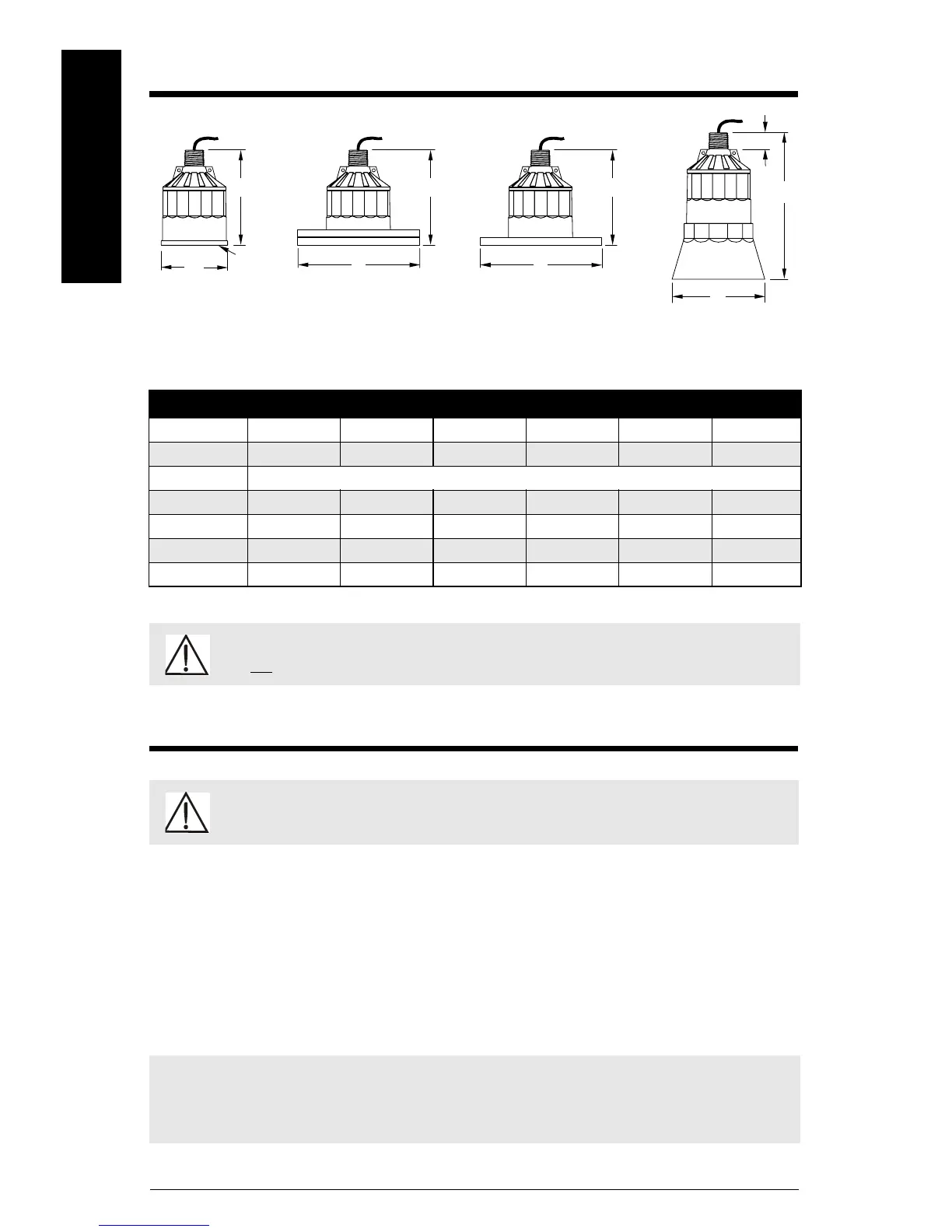
Outline and Dimensions
Mounting
• Mount the transducer so that it is above the maximum material level by at least the
blanking value. Refer to the associated controller manual.
• On liquid applications, mount the transducer face parallel to the liquid surface. On solids
applications, use a Siemens Milltronics Easy Aimer to help aim the transducer.
• Do not overtighten. Most applications require only hand tightening of the mounting
hardware. Connect a safety chain from the transducer to a structural member to secure
installation. Consider using the optional temperature sensor when a flanged transducer
is used, when a fast temperature response is required, or in high temperature vessels.
Dimension XPS-10 XPS-15 XPS-30 XPS-40 XCT-8 XCT-12
A 88 mm (3.4") 121 mm (4.8") 175 mm (6.9") 206 mm (8.1") 88 mm (3.4") 121 mm (4.8")
B 122 mm (4.8") 132 mm (5.2") 198 mm (7.8") 229 mm (9.0") 122 mm (4.8") 132 mm (5.2")
C to suit ANSI, DIN and JIS standards
D* 128 mm (5.0") 138 mm (5.4") 204 mm (8.0") 235 mm (9.2") 128 mm (5.0") 138 mm (5.4")
E 124 mm (4.9") 158 mm (6.2") n / a n / a n / a n / a
F 152 mm (6.0") 198 mm (7.8") n / a n / a n / a n / a
G 28 mm (1.1") 28 mm (1.1") 28 mm (1.1") 28 mm (1.1") 28 mm (1.1") 28 mm (1.1")
* nominal
WARNING: Optional Split Flange, Bonded Flange, and Easy Aimer configurations
are not suitable for pressure applications.
WARNING: Special handling precautions must be taken to protect the
face of the transducer from any damage.
Note: For pressure tight applications, install transducers hand tight plus ½ turn to 1½
turns. PTFE tape or other appropriate sealant may be used to aid in sealing the threads for
use in pressure applications.
B
A
C
B
F
E
C
D
G
standard
radiating
face
optional bonded flange
refer to associated instructions
optional split flange
refer to associated instructions
optional
submergence shield
refer to associated
instructions

 Loading...