Operating Manual of FC18 Controller
Page: 10/70
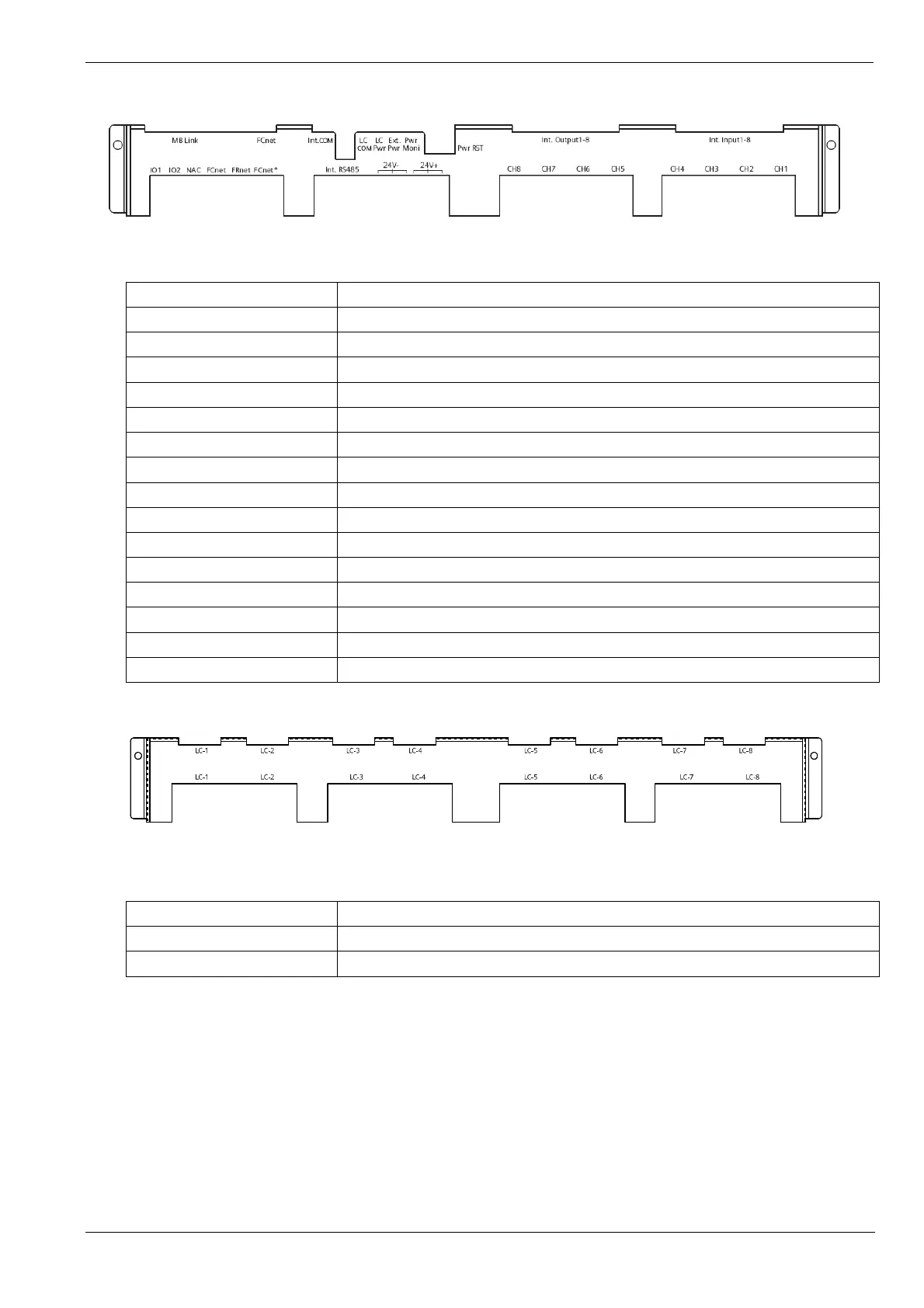
Fig. 2-3 Terminal board of main unit
Table-2-2
Sign Description
MB link /FCnet(upside)
Connect to “MB Link” port on main unit
Int. COM Reserved
LC COM Connect to line card for communication
LC Pwr Connect to line card for power supply
Ext. Pwr Connect to 24VDCpower supply
Pwr Moni Connect to port “PWR. MNTR” on main unit
Pwr RST Undefined
Int. Input /Int.Output Connect to the interlocking panel on main unit
IO1/IO2
Programmable input\output(see to Fig.2-9)
NAC
Connect to NAC alarm(see to Fig.2-8)
FCnet
Connect to controller(see to Fig.2-7)
FRnet
Connect to floor repeater display FRT/Mimic driver(see Fig.2-6)
Int.RS485 Reserved
24V-/24V+ Used for manufacture test (internal use only)
CH1-8
Connect to 8 channels of interlocking panel(see Fig.2-10)
Fig 2-4 Terminal board of line card
Table 2-3
Sign Description
LC-1/2/3/4/5/6/7/8(upside)
Connect to the line card
LC-1/2/3/4/5/6/7/8(underside) Connect to the field device(see Fig.2-5)

 Loading...


