Operating Manual of FC18 Controller
Page: 12/70
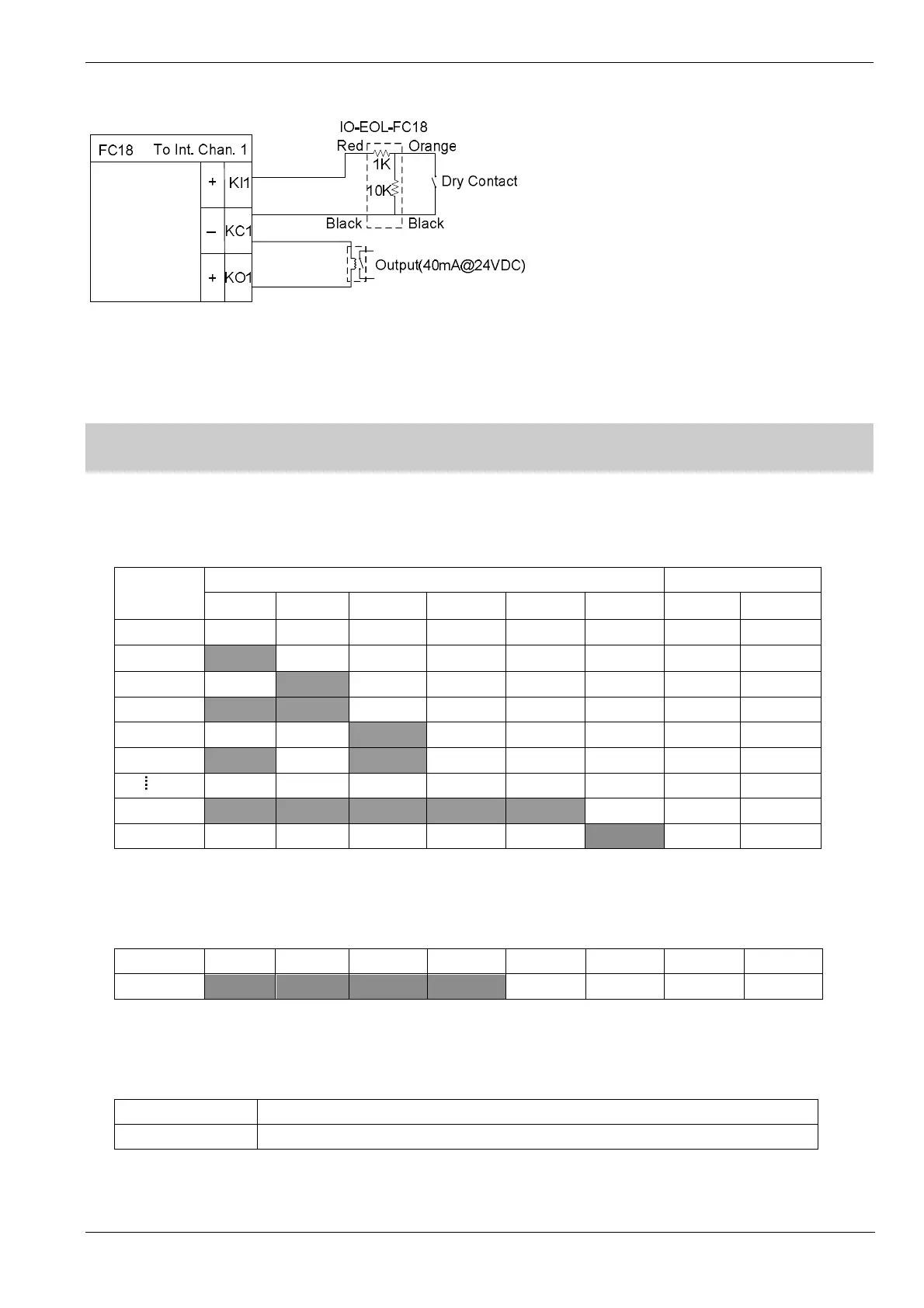
Fig. 2-10 Interlocking panel connection diagram (the same for other channels)
Note: the load range of each output is 24VDC, 600Ω – 1.2kΩ
3. DIP-SWITCH
There is a 8-digit Dip-switch FCnet ID (Fig. 2-2) on main unit. The 1-6 digit of Dip-switch is available, used to set 1-32
address of main unit. The 7-8 digit must be “Off”.
Table 2-4
FCnet
Address
Dip-Switch Reserved
1 2 3 4 5 6 7 8
Null Off Off Off Off Off Off Off Off
1
On
Off Off Off Off Off Off Off
2 Off
On
Off Off Off Off Off Off
3
On On
Off Off Off Off Off Off
4 Off Off
On
Off Off Off Off Off
5
On
Off
On
Off Off Off Off Off
31
On On On On On
Off Off Off
32 Off Off Off Off Off
On
Off Off
There is a 8-digit Dip-switch Int. ID (Fig. 2-2) on interlocking panel .The 1-4 digit of Dip-switch is available, used to set
address of interlocking panel. The address No. is fixed as 15. The 5-8 digit is “Off”.
Table 2-5
Address D1 D2 D3 D4 D5 D6 D7 D8
15
On On On On
Off Off Off Off
There is a 2-digit Dip-switch CAN End (Fig. 2-2) on main unit. It is used to set 120Ω EOL resistor of FC18-BUS and
FR18-BUS.
Table 2-6
1
On:FC18-BUS EOL is connected; Off:not connected
2
On:FR18-BUS EOL is connected; Off:not connected

 Loading...


