Operating Manual of FC18 Controller
Page: 9/70
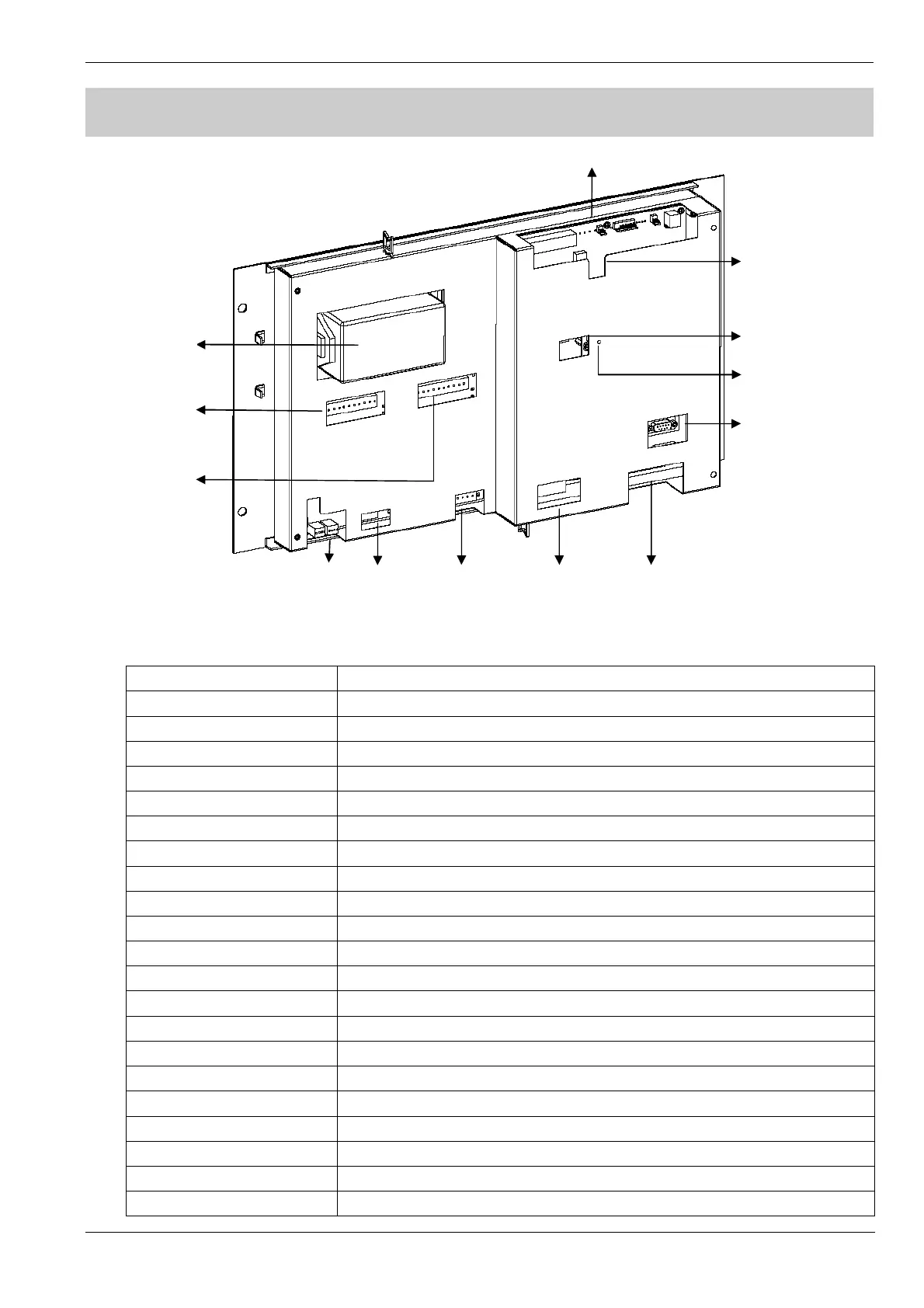
2. CONNECTION DIAGRAM
图 2-2 Back side of Main Unit
Table 2-1
Sign Description
MB Link Connect to “MB Link” port on terminal board of main unit
Ext. Reserved
Pwr. Mntr. Connect to “Pwr Monitor” port on terminal board of main unit
Pwr. Status Connect to “Signal monitor” port on power supply
Printer Pwr. Connect to printer
MB Pwr. Connect to “PS” port on main unit
CAN End Dip-switch, used to set EOL resistor of FC18-BUS/FR18-BUS
FCnet ID Dip-Switch, used to set FC18-BUS address no.
Reset Used to reset controller
CPU COM Connect to special converter module for download/upload software
LC-1/LC-2 Reserved
Int. COM Connect to port “RS485” on interlocking panel
LC COM Connect to line card
Printer COM Connect to printer
PS Connect to power supply and port “MB Pwr” on main unit
Int. ID Dip-Switch, used to set interlocking address no.
DL Used to download/upload interlocking software(internal use only)
RS485 Connect to port “Int.COM” on main unit
Int. Output 1-8 Connect to “Int. Output 1-8” port on terminal board of main board
Int. Input 1-8 Connect to “Int. Input 1-8” port on terminal board of main board
Printer Connect to printer
MB Link Ext. Pwr. Mntr. Pwr. Status Printer Pwr. MB Pwr.
CAN End
FCnet ID
CPU COM
Int. ID
Int. Output 1-8
Printer COM
PS
LC-1 LC-2 Int. COM LC COM
Reset
Printer
DL RS485

 Loading...


