Operating Manual of FC18 Controller
Page: 57/70
CHAPTER 4 MAINTENANCE
1. DAILY EXAMINATION
People on duty should examine controllers every day and record status. If there is alarm, trouble or other abnormal status,
please follow “Emergency and Trouble Handing”; when controller gets normal again, the event should be recorded.
2. TROUBLESHOOTING GUIDELINE
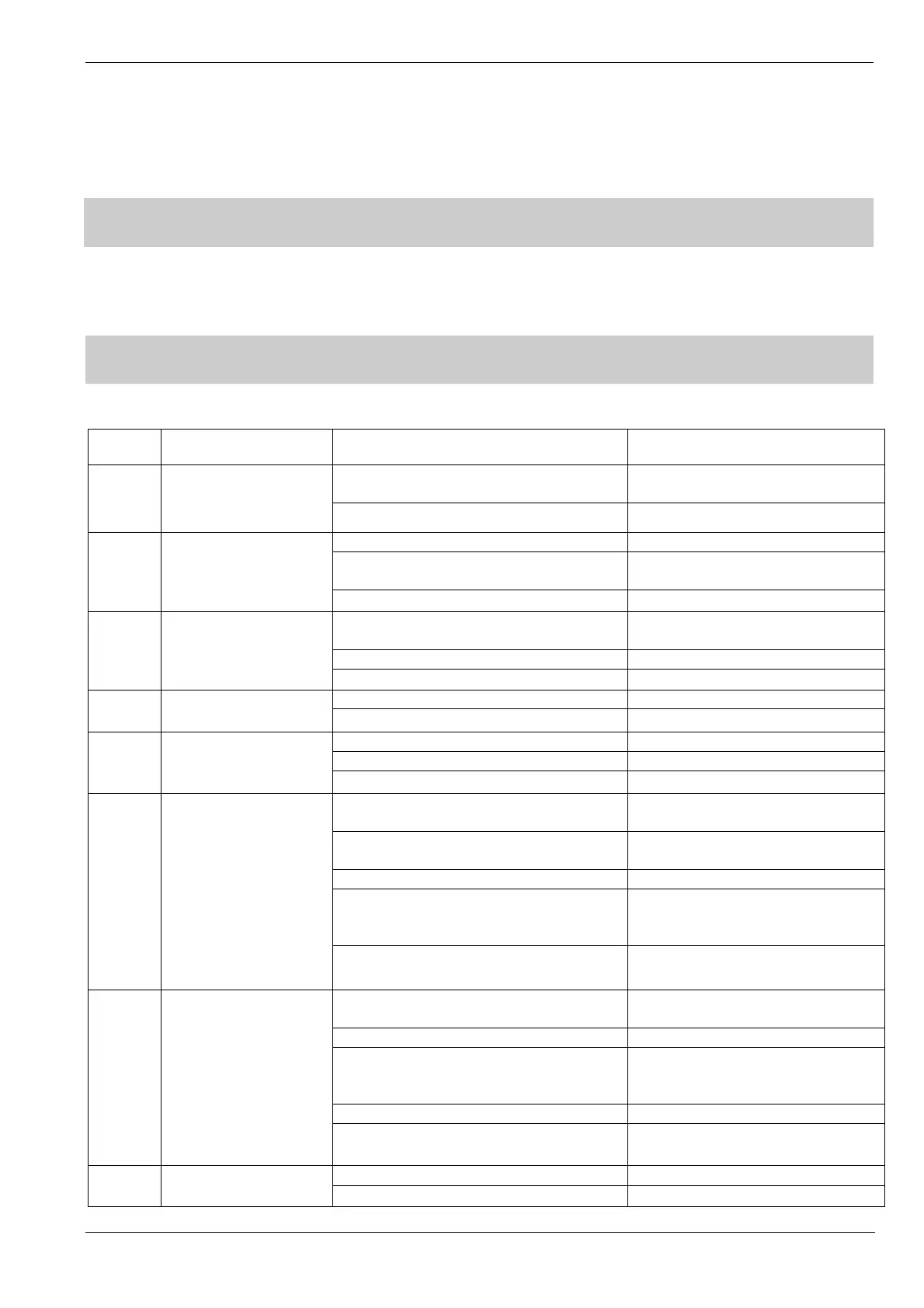
Table 4-1
No. Failure Status Cause Analysis Recommend Solving Method
1.
Function keys, LED,
LCD, etc. cannot work or
is damaged
Error of signal wirings/power wiring
connection;
Correctly and firmly connect wirings;
Corresponding hardware trouble; Change corresponding hardware;
2.
No power supply
indication
Whether main power and battery are on; Properly connect power wiring;
Whether power lines inside controller is firm
enough;
Check power wiring;
Power trouble; Change power supply;
3.
LCD is off ”black screen”
No power supply for LCD or power supply
component on main board is damaged;
Check power lines or change main
board;
LCD trouble; Change LCD;
Wire connection loosening Check the wire connection;
4.
LCD is on, but nothing is
displayed.
System software or configuration file is lost; Change corresponding software/file;
CPU trouble; Change CPU;
5.
No sound
No voltage; Change power lines or main board;
Sound volume is not enough; Adjust sound volume of buzzer;
Buzzer is damaged; Change buzzer;
6.
Station trouble
Configuration file does not consist with actual
equipment;
Change file;
Main board address is not set by dip-switch
or dose not consist with configuration file;
Set address by dip-switch or change
configuration file;
Main board damaged; Change main board;
If more than 2 controllers are connected,
check FC18-BUS communication and
configuration file;
Check FC18-BUS communication line;
Check whether FC-BUS EOL resistor is
connected;
Properly connect EOL;
7.
Interlocking panel
trouble
Configuration file does not consist with actual
equipment;
Change file;
Communication wries/power supply trouble; Properly connect wires;
Address is not set by dip-switch on
interlocking panel or does not consist with
configuration file;
Set address by dip-switch on
interlocking panel or Change
configuration file;
Interlocking panel is damaged; Change interlocking panel;
Check whether FR18-BUS EOL resistor is
connected;
Properly connect FR18-BUS resistor;
8.
Main board input/output
trouble
Configuration file is wrong; Change configuration;
Main board input/output port is damaged; Change main board;

 Loading...


