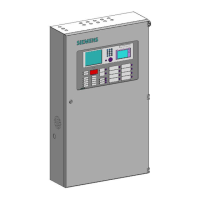
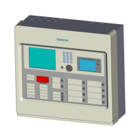
Operating Manual of FC18 Controller
Page: 64/70
APPENDIX 3 DEVICES GROUPING TABLE
Device type
Detecting
group
Control output
group
Supervision
group
FRT
group
FDO181 Smoke detector
√ √
FDT181 Heat detector
√ √
FDM181 Manual Call Point
√ √
FDCI181 Input module
√
FDCIO181 Input/output module
√
Main board supervision input
√ √
Main board confirmation input
√ √
Main board alarm input
√ √
Main board output, interlocking panel output (without
confirmation)
√ √
Main board output, interlocking panel output (with
confirmation)
√ √
NAC
√
Main power
√
Battery
√
Charging circuit
√
Printer
FDCL181 Isolator
√
Supervision input of FDCI181 Input module/ FDCIO181
Input/output module
√ √
Confirmation input of FDCI181 Input module/
FDCIO181 Input/output module
√ √
Alarm input of FDCI181 Input module/ FDCIO181
Input/output module
√ √
Output (without confirmation) of FDCI181 Input
module/ FDCIO181 Input/output module
√ √
Output (with confirmation) of FDCI181 Input module/
FDCIO181 Input/output module
√ √
Note:
- One device can be assigned to max. 10 groups AND 6 FRT groups.
- Relations among equipments of control output group is “and” relations. Relations among equipments of
supervision and detecting group is “or” relations.
- Alarm and trouble information of devices of FRT group can be displayed on the display panel.
- Devices must be put into groups to participate interlocking relation program.

 Loading...


