Installation of hardware
15
Building Technologies 007828_b_en_--
Fire Safety & Security Products 09.2008
5 Installation of hardware
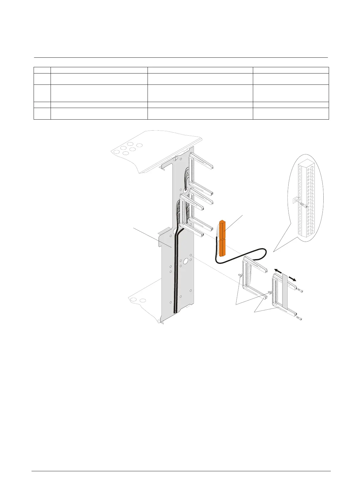
5.1 Installation of auxiliary p.c.b. chassis
Pos. Module Preparation Default
1 Module chassis Screw module chassis provisory on the housing
front panel (mount again later) see chapter 15
Mounted in housing
2 Connection cable with terminal block
Z3I1050 or terminal block with p.c.b. chas-
sis Z1K030
Mount on module chassis –
3 Screw ground connection to pin 11 Mount on module chassis –
4 Attach connection cable with plug-in termi-
nals
To terminal block Z3I1060 (according to system
documentation)
–
Z3I1050
Z1K030
1
4
2
C
B
A
3
2
0
1
2
3
4
5
6
7
8
9
1
0
1
1
1
2
1
3
1
4
1
5
1
6
1
7
1
8
1
9
Legend:
A = EMI contaminated area
B = EMI protected area
C = EMI protection
 Loading...


