Control terminal and floor repeater panels
22
Building Technologies 007828_b_en_--
Fire Safety & Security Products 09.2008
10 Control terminal and floor repeater panels
10.1 FT700A (B3Q700) Control terminal
Control terminal see chapter 6
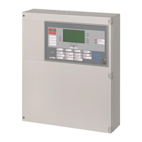
10.2 B3R051 Parallel indicator panel
Pos. Module Preparation Default
1 Resistor array 'N3' Remove all but 1 device, see description in
document 007831
Equipped
2 Programming switch 'S1': Equipment ad-
dress
Set according to the system documentation, the
device address is determined by the wiring
order
Address 0 (Test procedure)
3 Inscription strips Inscribe user data and insert inscription strips No inscription
Created with Word template DOT
(document 007874)
1
S1
2
N3
1
24
3
Î Connect data bus and supply cable, installation -> see document 007827
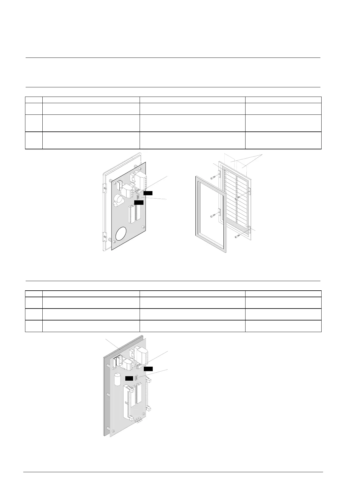
10.3 K3R072 Synoptic p.c.b.
Pos. Module Preparation Default
1 Mounting plate Remove according to the system documenta-
tion, see description in document 007831
Mounted
2 Resistor array 'N3' Remove all but 1 device, see description in
document 007831
Equipped
3 Programming switch 'S1': Equipment ad-
dress
Set according to the system documentation Address 0 (Test procedure)
2
S1
3
N3
1
Î Re-install card on mounting plate, connect data bus and supply cable as well as
the peripheral equipment.
 Loading...


