Control terminal and floor repeater panels
23
Building Technologies 007828_b_en_--
Fire Safety & Security Products 09.2008
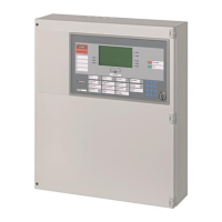
10.4 K3G060 Relay p.c.b.
Pos. Module Preparation Default
1 Mounting plate Remove according to the system documenta-
tion, see description in document 007831
Mounted
2 Programming connectors 'X1'.... 'X24':
Programming of external potential + or – to
relay contact
Set according to the system documentation, see
description in document 007831
'Open' (relay contact is potential-
free)
1
X1
2
X24
Î Re-install card on mounting plate, connect data bus and peripheral equipment.
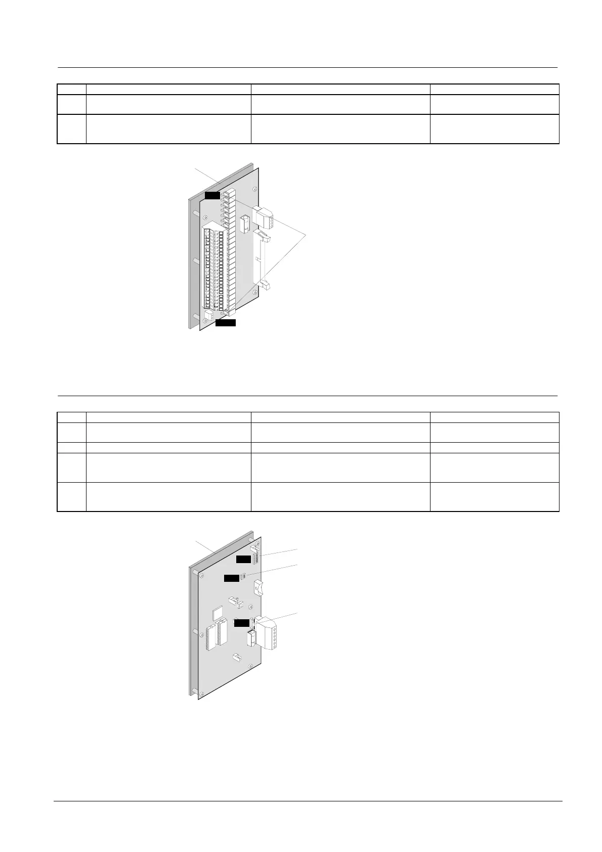
10.5 K3I050 LON/Synoptic p.c.b.
Pos. Module Preparation Default
1 Mounting plate Remove according to the system documenta-
tion, see description in document 007831
Mounted
2 Programming switch 'S3': LON-Bus address Set according to the system documentation Address 0
3 Programming switch 'S4-1': Define LED
settings of the data bus devices
Set to 'ON' when the LED of the data bus de-
vices shall flash (only for devices with address
5... 8)
To 'OFF'
4 Resistor 'R1': line termination element
'LON-Bus'
Stub line: if K3I050 is not the last device, re-
move resistor 'R1', see description in document
007831
Inserted 100Ω
1
S3
2
S4
R1
3
4
Î Re-install card on mounting plate, connect data bus and LON-Bus cable; supply
cable as well as the peripheral equipment.
 Loading...


