FXS901 User Manual
A6V10336897_d_en_ 25/49
5.15 HOW TO CREATE A CONTROL LOGIC
FXS901 software provides 7 kinds of control logic:
· Basic control
· Advanced control
· User control
· LED control
· Releasing control
· Mimic control
· Test control
The table below shows the differences:
Control Cause Effect
Basic control OR / AND / SUM All effects get active at the same time when cause
conditions are fulfilled.
Advanced control OR Effect gets active based on “NotificationEventType”
setting when cause conditions are fulfilled.
User control OR / User level Effect gets active based on “Command list” setting
when user level activates.
LED control - Effect gets active when cause conditions are
fulfilled.
Releasing control
and 2)
OR / AND When “Immediately” is selected, effects get active
at the same time when cause conditions are
fulfilled. When “ReleaseSync” is selected, the
system operates simultaneously with the releasing
channel.
Mimic control OR The LED status changes with the status of the
cause.
Test control OR When cause conditions are fulfilled, the selected
channels under Effect are activated. A maximum of
4 input channels are supported for test control and
the 4 channels are selected in Property by default.
The 4 channels (Active Channel 1, 2, 3 and 4)
correspond respectively to the devices listed under
Hardware tree in order from top to bottom.
The steps below describes the case when the devices under “Automatic Alarm Zone 2” and “Automatic Alarm
Zone 3” release an alarm at the same time, the output or “Effect” of (Intelligent Control @2) is activated.
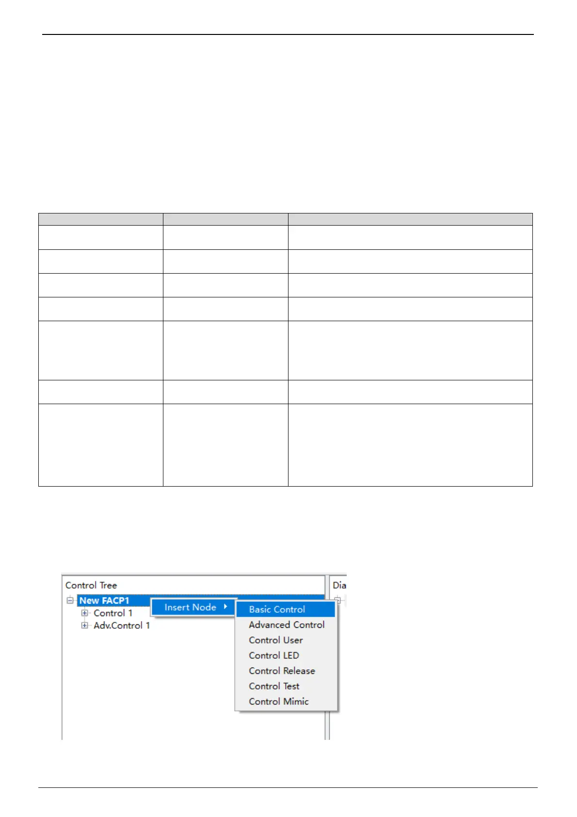
1. Right click “New FACP1” under the Control tree and then click “Insert Node”. Select the wanted control
logic (take Basic control as an example). The new control logic “Control 2” is added and displayed under
“New FACP1” and on the Children view.
2. Select “Cause (OR)” under Control 2, right click on it, then click “Insert Node”. “Cause Fire Calculation”
and “Cause Fire Status Tracer” are listed. “Cause Fire Calculation” is used to define “OR/AND/SUM” logic.

 Loading...