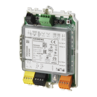
3.2.3.2 Status display for the lines
There are both red and green LEDs for each input/output and these are used to
indicate the status (LED 'I/O 1' and 'I/O 2'). Their meaning depends on how the
input/output is configured.
Input/output is configured as an input
(detector line or contact input)
Green
'I/O 1' / 'I/O 2'
(Ref 10 / 9)
Red
'I/O 1' / 'I/O 2'
(Ref 10 / 9)
Off Off Not active
No supply
Incorrectly configured
ON Off Standby
Off ON Alarm
ON ON Fault:
Open line
Short-circuit
Deviation in terms of monitoring
resistances (only in the case of a contact
input)
Off Flashes Triggered in inspection mode/test mode
What the LEDs mean (detector line or contact input)
Input/output is configured as an output (control line)
Green
'I/O 1' / 'I/O 2'
(Ref 10 / 9)
Red
'I/O 1' / 'I/O 2'
(Ref 10 / 9)
Off Off Not active
No supply
Incorrectly configured
ON Off Standby
Off ON Output activated
ON ON Fault:
Open line
Short-circuit
Control line not calibrated
Off Flashes Inspection mode/test mode
Flashes every
0.5 s
Off Calibration of load resistances
Off ON for 2 seconds Calibration of load resistances not permitted
What the LEDs mean (control line)
 Loading...
