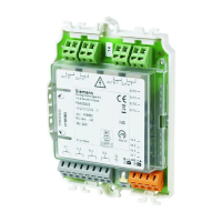
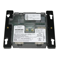
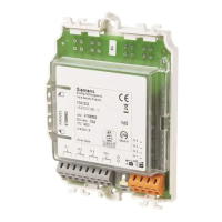
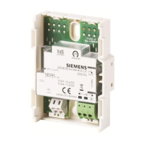
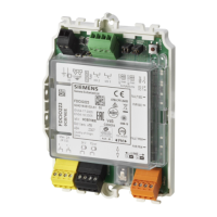
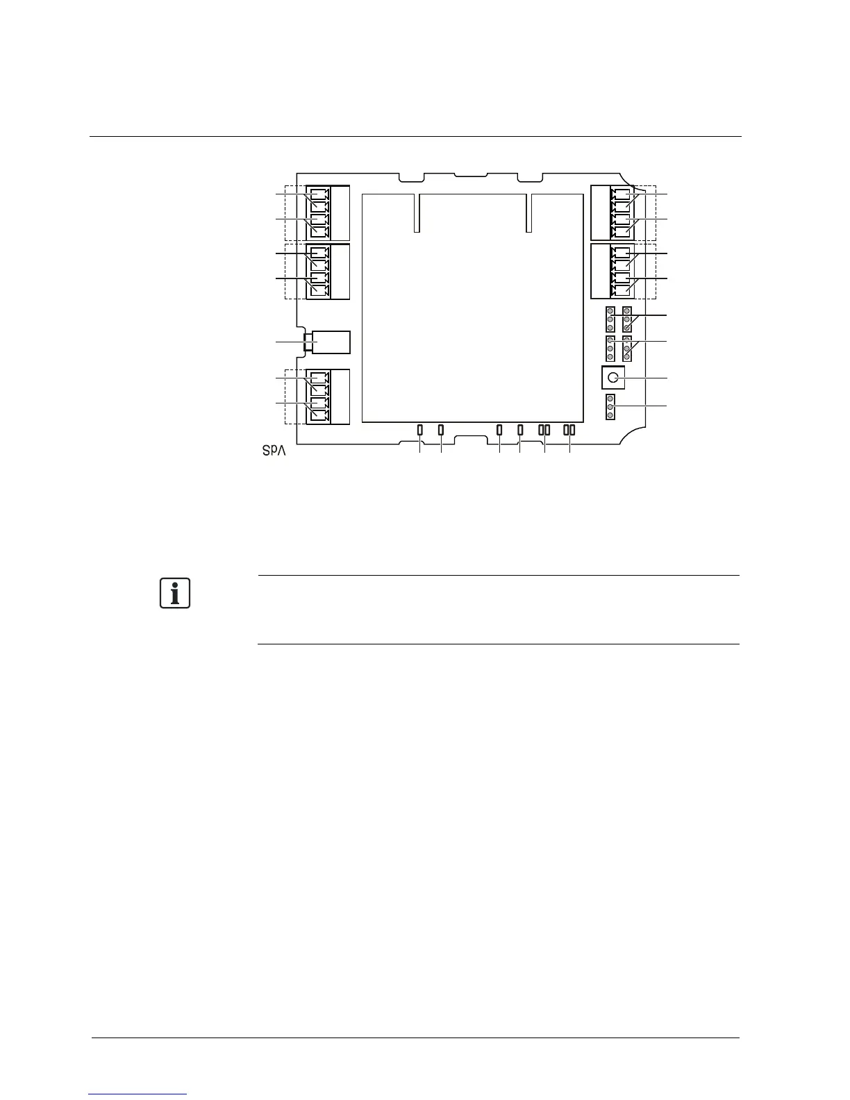
Circuit board view
Connect the module in accordance with the corresponding connection diagrams.
Note the positive and negative poles.
Only connect one wire per terminal. This is the only way to ensure the connection
is failure-free for the entire service life of the device.
When connecting the device, consider the following:
The shielding of the FDnet/C-NET detector line must be connected to
terminal 15.
The shielding of the 24 V secondary side supply must be connected to
terminal 16.
The grounding for the shielding on the secondary side must be connected to
terminal 1, as must the secondary side ground fault monitoring.
The shielding for the lines on the secondary side should be connected to
terminal 2.
In the case of shielding on the secondary side, the secondary-side grounding
must be connected. If there is no local station ground available, the shielding for
the secondary-side supply can be used as a ground instead.
 Loading...