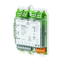
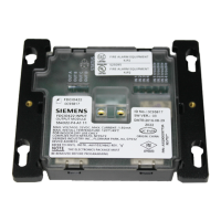
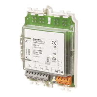
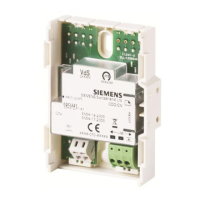
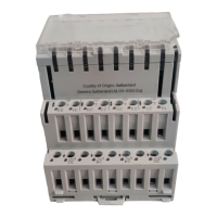
5 Mounting / Installation
The procedure followed during mounting depends on whether the input/output
module FDCIO223 is installed with or without a housing.
Module overheating and damage
A minimum clearance of 1 cm must be observed between two modules or
between the module and any other boundary.
5.1 Installation with housing
Note the positive and negative poles.
Only connect one wire per terminal. This is the only way to ensure the connection
is failure-free for the entire service life of the device.
The module can be installed at any location, along with the separate FDCH221
housing.
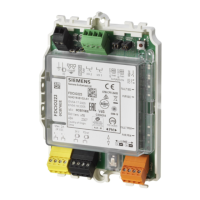
When installing the module in the housing FDCH221, proceed as follows:
1. Break out the required cable entries.
2. Install housing on a flat surface.
3. Insert cables. If necessary, fasten the cables using the M20 x 1.5 cable glands
or use a different cable entry.
4. If you are using shielded cable, join the shielding to the DBZ1190-AB
connection terminal. The shielding must not touch any extrinsic earthing
potentials or metal parts in the housing.
5. Install the module in the housing using the fixing screws supplied.
6. Connect cables to corresponding terminals (see connection diagram).
7. Close housing using supplied screws.
 Loading...
