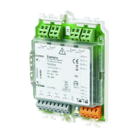
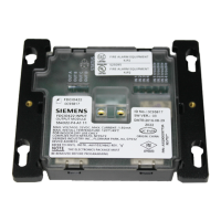
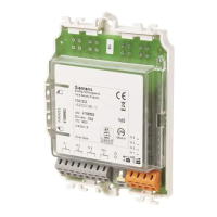
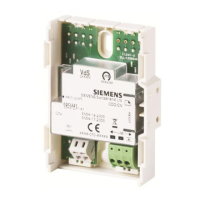
Notes
Only the settings detailed above are permitted.
The jumpers must remain inserted at all times.
For monitoring, both of an input/output's jumpers must remain in the same
position at all times.
The jumpers only need to be in the 'invert' (reverse polarity) position in the case
of control involving reverse-polarity monitoring. For all other applications, the
jumpers must be in the 'norm' (identical polarity) position.
All other settings are made using the engineering tool.
The control line is not monitored in the activated (connected) state.
3.3 Function
3.3.1 Overview
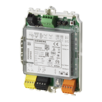
A distinction is made in terms of the function between the primary and secondary
sides of the FDCIO223 input/output module. The primary side represents the
connection to the FDnet/C-NET. Both inputs/outputs are triggered on the
secondary side.
The inputs/outputs can be used as follows:
GMT Siemens/Cerberus collective detector lines
GMT SynoLINE300 collective detector lines
Control lines
Contact inputs
 Loading...
