Planning the control line
Polarity of control and monitoring
systems in relation to one another
□ Same polarity
□ Reverse polarity
□ Same polarity
□ Reverse polarity
Activation period/behavior □ Permanent
□ Only for the period of: ___ s (1 … 20 s)
□ Symmetrical pulse pattern
□ Permanent
□ Only for the period of: ___ s (1 … 20 s)
□ Symmetrical pulse pattern
Behavior in the event of a
communication problem involving
the control panel
□ Control remains the same as before the error
□ Control is activated
□ Control is deactivated
□ 'Degraded mode horn' function (only possible
with FS20/FS720)
□ Control remains the same as before the error
□ Control is activated
□ Control is deactivated
□ 'Degraded mode horn' function (only possible with
FS20/FS720)
Planning contact input
Type of input □ Danger input
□ Status input
□ Danger input
□ Status input
Monitored for □ Open line
□ Short circuit and open line
□ No monitoring
□ Open line
□ Short circuit and open line
□ No monitoring
Input active, when contact is □ Open
□ Closed
□ Open
□ Closed
Filter time Duration: ____s (0.5 … 240 s) Duration: ____s (0.5 … 240 s)
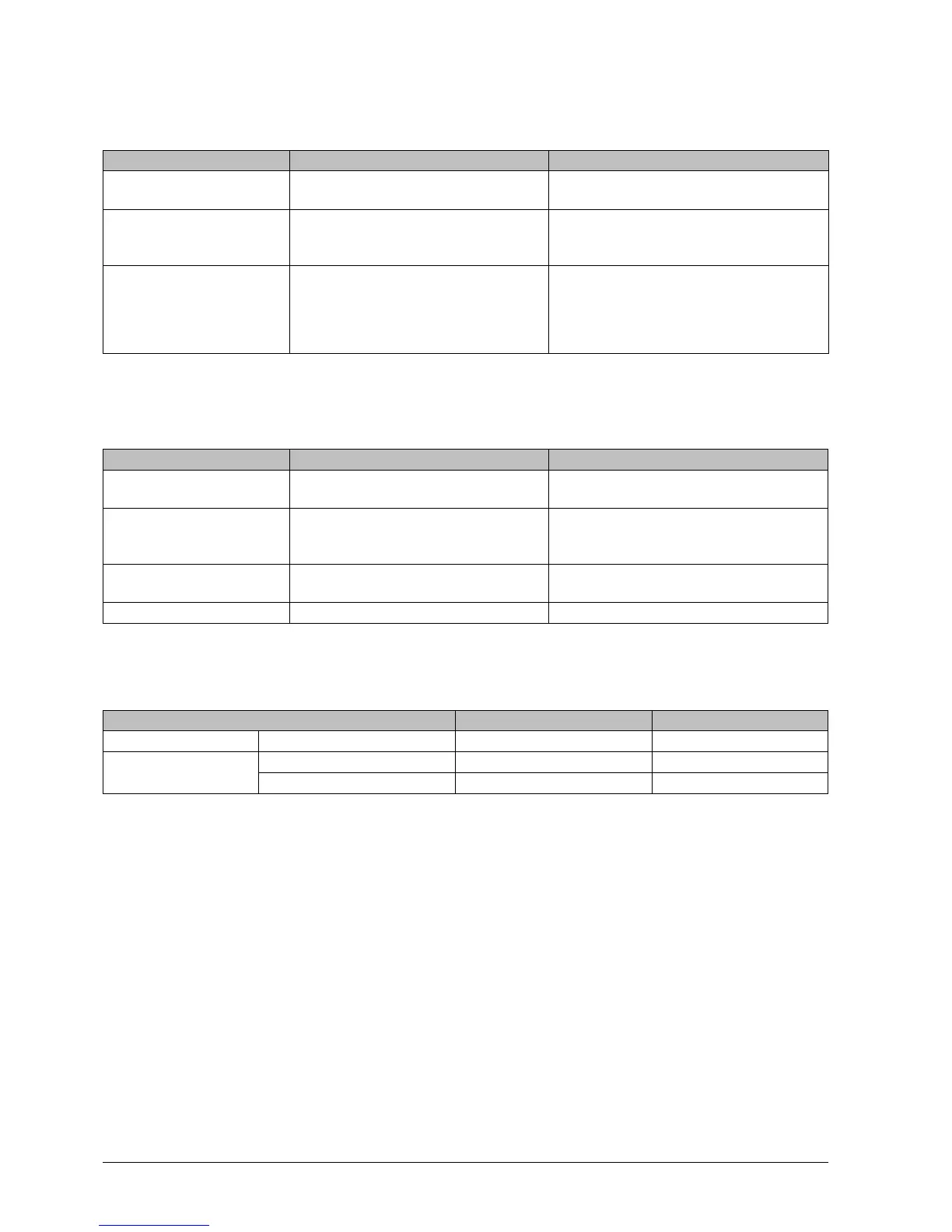
Determining the fuses
Two inputs/outputs active
Primary side 24 V supply Max. 1.5 AT
1
Max. 2 AT
1
Secondary side Input/output 'I/O 1' Max. 1.5 AT
1
Max. 1 AT
1
Input/output 'I/O 2' Max. 1.5 AT
1
Max. 1 AT
1
1
The fuse value must be adapted to the respective load.
The maximum specified fuse value must not be exceeded.
Use 'slow-blow' fuses.
 Loading...