Installation
16
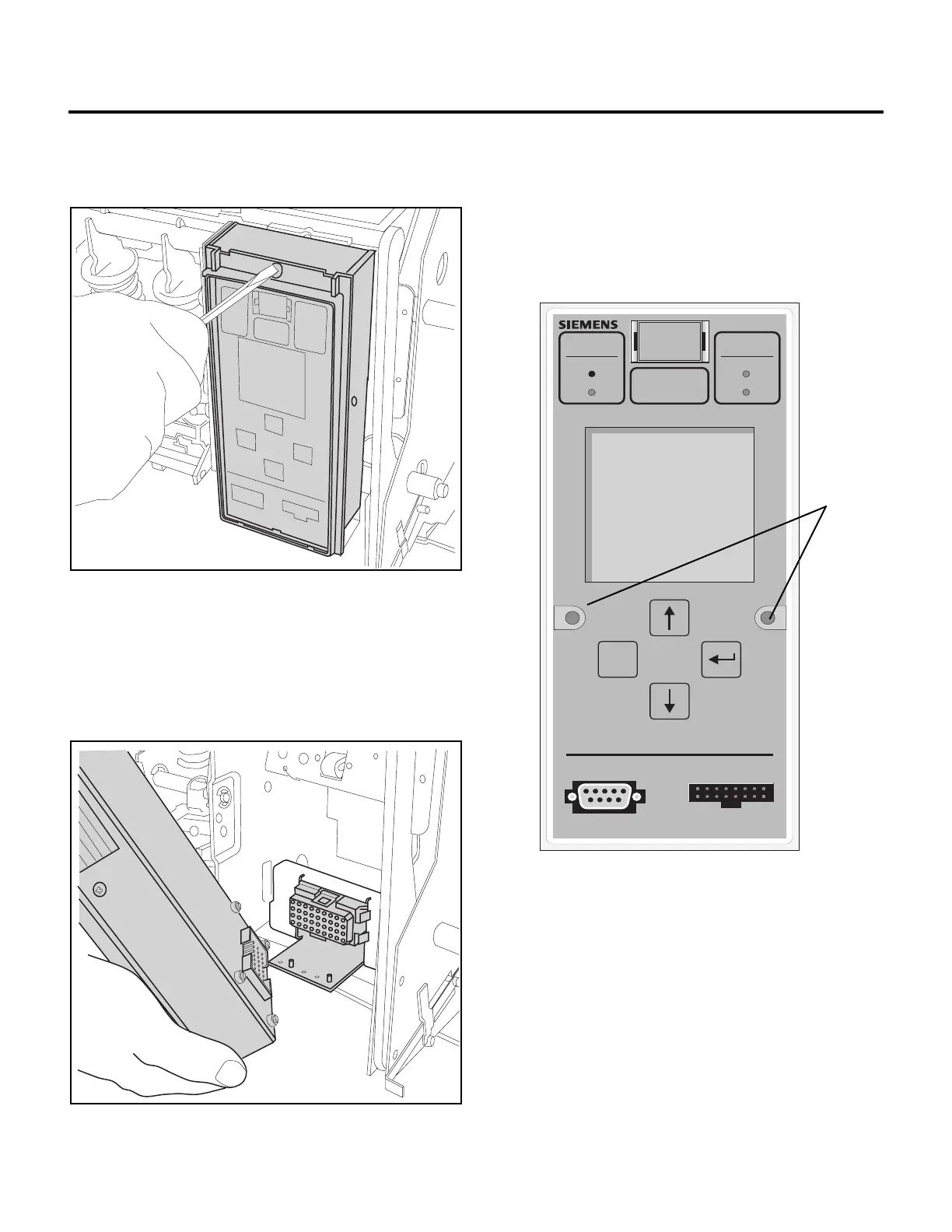
2. Remove the trip unit retaining screw.
Remove the front cover of the breaker and trip unit retaining
screw. Lift the trip unit from the support plate and unmate the
connector. Note that the trip unit must be lifted from the support
plate high enough for the pins on the support plate to clear the
holes in the bottom of the trip unit; otherwise, the connector
cannot be unmated.
3. Remove the trip unit.
2.10 Starting Up
1. Remove the screws from the seals to access the display
interface keypad.
The screws are on both sides of the display shield as shown
below.
2. Turn on external 120 VAC control power. The “Protective”
light flashes when the protection functions are operational.
The “Meter” light flashes when the metering functions are
operational. Now you are ready to learn how to use the
front panel to configure the trip unit for protection and
metering.
MAX Rating
2000 A
System
Status
System
Check
Tripped Protective
Alarm Meter
Rating Plug
I
n
= 1600 A
ESC
Serial Port Test Connector
Screw
Locations
 Loading...


