Extended Protective Relaying
38
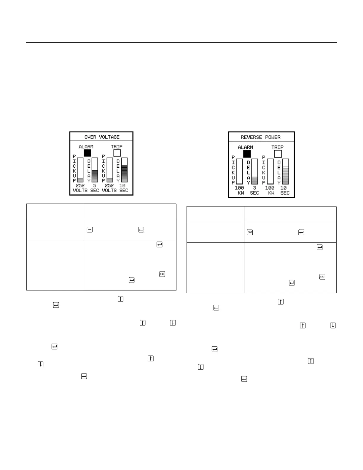
7.7 Overvoltage
If the amount of voltage on any phase goes above a specified
level, the trip unit can alarm or trip by setting the parameters
from the
Over Voltage
selection of the
Protective Relays
Menu
. To alarm, or to trip and alarm, on overvoltage:
1. From the
Protective Relays Menu
, select
Over Voltage
.
The alarm checkbox is highlighted, but alarming has not
been set.
2. To enable alarming, press the Up Arrow key, then press
Enter . If you have enabled alarming, a checkmark
appears and the pickup settings are highlighted.
3. Select a pickup value by pressing the Up or Down
Arrow keys until the value is at the desired level. The pos-
sible pickup values depend on the rating of the breaker;
see the table in the appendix,
Parameter Settings
. Press
Enter .
4. Then select a delay time by pressing the Up or Down
Arrow keys until the value is at the desired level. Possi-
ble time delay settings are 1, 2, 3, 4, 5, 7, 10 and 15 sec-
onds. Press Enter .
7.8 Reverse Power
If the amount of reverse power goes above a specified level,
the trip unit can alarm or trip by setting the parameters from the
Reverse Power
selection of the
Protective Relays Menu
. To
alarm, or to trip and alarm, on over reverse kilowatts:
1. From the
Protective Relays Menu
, select
Reverse Power.
The Alarm checkbox is highlighted, but alarming has not
yet been set.
2. To enable alarming, press the Up Arrow key, then press
Enter . If you have enabled alarming, a checkmark
appears and the pickup settings are highlighted.
3. Select a pickup value by pressing the Up or Down
Arrow keys until the value is at the desired level. The pos-
sible pickup values depend on the rating of the breaker;
see the table in the appendix,
Parameter Settings
. Press
Enter .
4. Then select a delay time by pressing the Up or Down
Arrow keys until the value is at the desired level. Possi-
ble time delay settings are 1, 2, 3, 4, 5, 7, 10 and 15 sec-
onds. Press Enter .
5. Refer to the individual PT Module instruction sheet for PT
Module connections for bottom-fed breakers.
If you want to
enable...
Then...
alarming only follow steps 2–4 and press Escape
. Then press Enter at the verifi-
cation screen.
alarming and tripping follow steps 2–4, press Enter to
highlight the Trip checkbox, then
repeat the process you used in
steps 2–4 to set pickup and delay
values. After setting both the alarm
and trip values, press Escape .
Then press Enter at the verifica-
tion screen.
 Loading...


