Overcurrent Protection Configuration
26
5.4 Short Time Fault Protection
The short time setting establishes the maximum current level at
which the circuit breaker will operate for brief durations without
initiating a tripping sequence. Two values must be set to
provide this protection: the continuous current Pickup and the
Delay.
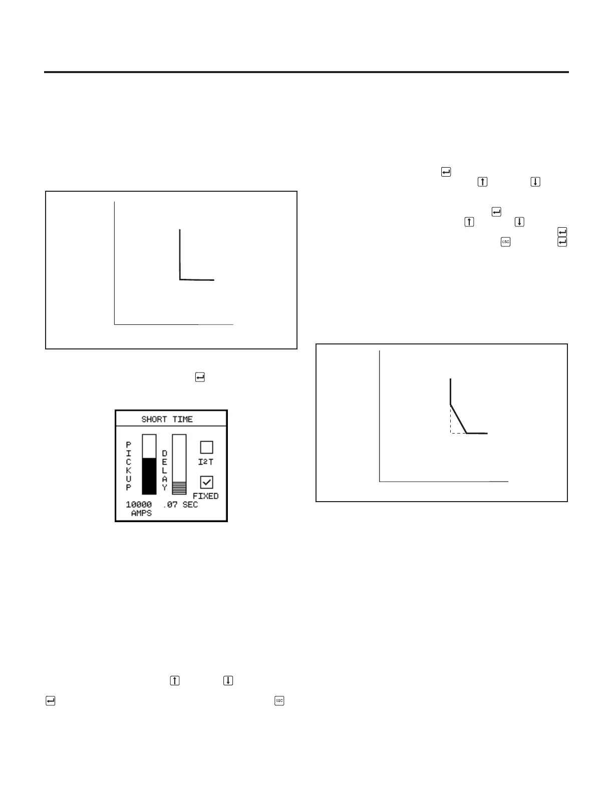
To select short time fault protection, from the
Protective Menu
select
Short Time
and press Enter . The following screen
appears:
The short time pickup sets the maximum level of current the cir-
cuit breaker is allowed to carry for a short period of time with-
out tripping. This pickup, together with the short time delay,
allows downstream circuit breakers time to clear short circuit
faults without tripping the upstream circuit breakers. When the
pickup level is exceeded, the trip unit initiates the short time
fault protection sequence. On trip units for the 1200A and
2000A breaker frame sizes, the short time pickup may be set to
1.5, 2, 2.5, 3, 4, 5, 6, 7, 8, or 9 times the rating plug, I
n
. On trip
units for the 3200A and 5000A breaker frame size, the short
time pickup may be set to 1.5, 2, 2.5, 3, 3.5, 4, 5, 6, 7, or 8
times I
n
.
To program this value from the front panel, with the PICKUP
scale selected, press the Up or Down Arrow until the
scale shows the desired value. When displayed, press Enter
to go to the DELAY parameter or press Escape to
accept these settings.
The short time delay setting is used to set the time interval the
breaker will wait before initiating a trip command at the current
value selected on the short time pickup setting. This setting
has two modes of operation: a fixed delay, and an inverse I
2
t
ramp delay.
To set the mode, press Enter until the I
2
T and the FIXED
checkbox is highlighted. Press the Up or Down Arrow
key so that a check appears in the desired selection box.
To program the delay value, press Enter until the
Delay
parameter is selected. Press the Up or Down Arrow key
until the scale shows the value. When selected, press Enter
to go to the mode parameter or press Escape then Enter
to accept these settings.
The I
2
t ramp delay has the characteristic of being inversely
proportional to the square of the magnitude of the overcurrent
condition. This means that higher overcurrent conditions have
shorter delays and conversely lower overcurrent conditions
have longer delays. This characteristic can provide better
coordination with downstream circuit breakers and fuses.
In the fixed delay mode, the short time delay may be set to
0.07, 0.1, 0.15, 0.2, or 0.3 seconds.
In the inverse I
2
t ramp short time delay mode, the delay may
be set to a calibrated value of 0.07, 0.10, 0.15, 0.2, or 0.3
seconds at a current equal to 8 times I
n
.
 Loading...


