9 – 109
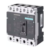
Wyłącznik z modułem COM15
(1) Jedynie w przypadku więcej niż 2 modułów CubicleBUS:
Przewody łączące X8 oraz pierwszy moduł CubicleBUS,
zapewniające zasilanie 24 V DC
(2) Kable łączące moduły CubicleBUS
(3) Moduły CubicleBUS
(4) Rezystor obciążający 120
Ω 0,5 W
(5) Kable połączeniowe zasilania 24 V DC
(6) Kabel połączeniowy, łączący moduł COM15
oraz pierwszy moduł CubicleBUS (z dwoma wtykami RJ)
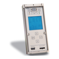
(7) Moduł COM15
Zasady konfiguracji
3 x 0,5
The value 0.1 is set if the
rotary switch is positioned in this
area of the rotation angle
Należy ustawić wartość 0,1 za pomocą
przełącznika obrotowego, ustawiając go
w polu przedstawionym na rysunku.
Circuit-breaker with COM15-module
(1) Only if there are more than 2 CubicleBUS-modules:
Connecting cables between the X8 and the first
CubicleBUS module for 24 V DC voltage supply
(2) Connecting cables between
CubicleBUS-modules
(3) CubicleBUS-modules
(4) Termination resistor 120
Ω, 0.5 W
(5) Connecting cables between
CubicleBUS-modules for 24 V DC
voltage supply
(6) Connecting cable between COM15 and the first
CubicleBUS module (with trwo western plugs)
(7) COM15
Setting principle

 Loading...


