Wiring
4.2 Block diagram
Interface module IM 155-5 MF HF (6ES7155-5MU00-0CN0)
32 Equipment Manual, 11/2023, A5E53268530-AA
4.2 Block diagram
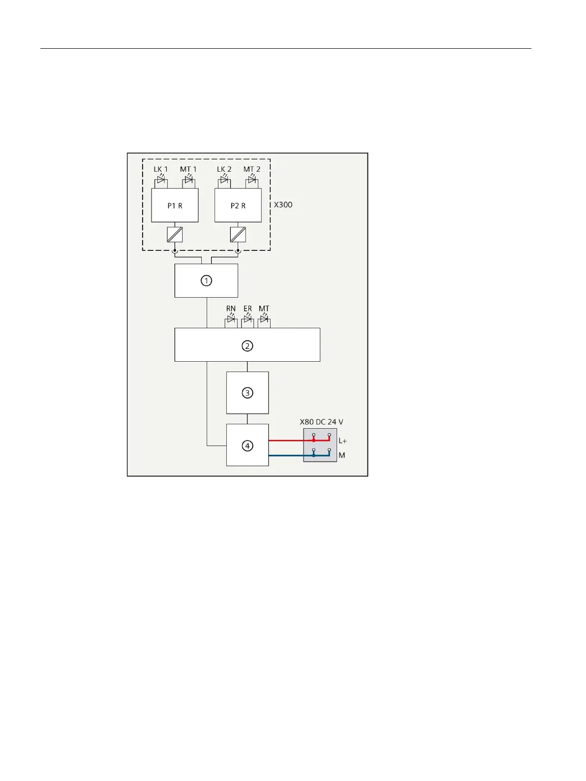
Schematic circuit diagram
② ET 200MP backplane bus interface
M Ground
④ Internal power supply MT 1,2 MAINTENANCE FiberOptic LED (SCRJ
X80
Supply voltage infeed RN RUN LED (green)
X5 BusAdapter
(For BusAdapters with RJ45 interface,
the shielding is connected to func-
ER ERROR LED (red)
PROFINET interface X1 Port 1
PROFINET interface X1 port 2
Figure 4-1 Schematic circuit diagram of the IM 155-5 MF HF interface module

 Loading...


