Interrupts and diagnostic, error, and system alarms
6.3 Alarms
Interface module IM 155-5 MF HF (6ES7155-5MU00-0CN0)
Equipment Manual, 11/2023, A5E53268530-AA
53
The interface module signals a maintenance event to the higher-level diagnostic system in
the case of the following events:
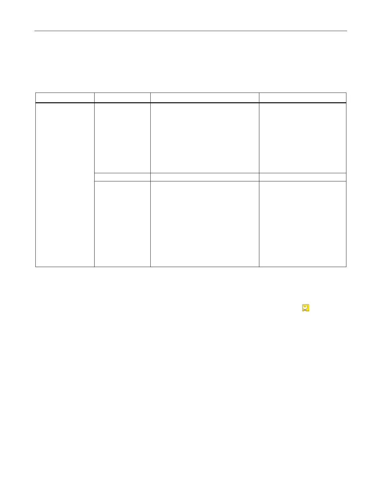
Table 6- 3 Triggering of a maintenance event
manded
MAINT LED is lit
• No synchronization frame received
No synchronization frame was re-
ceived by the sync master within the
timeout period after parameter as-
signment or during operation.
• Successive synchronization frames are
located outside permitted limits (jit-
ter)
The maintenance event is handed over.
tenuation that is too
high
• Fiber-optic error
• Attenuation through the fiber-optic
cable is already so high that operation
will soon no longer be possible.
1. Replace the fiber-optic cable
if damaged or aged.
2. Ensure the correct installa-
tion of the PROFINET con-
nectors or PROFINET
connections.
3. Adhere to maximum length
of 50m for POF cable or
100m for PCF cable.
4. Ensure that the FOC con-
nectors fit securely.
System alarms in STEP 7
The maintenance information is generated in STEP 7 with the following system alarms:
• Maintenance demanded - indicated for each port by a yellow wrench icon
in the
device view or in the hardware configuration.
You can find additional information in the STEP 7 online help.

 Loading...


