Interrupts and diagnostic, error, and system alarms
6.3 Alarms
Interface module IM 155-5 MF HF (6ES7155-5MU00-0CN0)
56 Equipment Manual, 11/2023, A5E53268530-AA
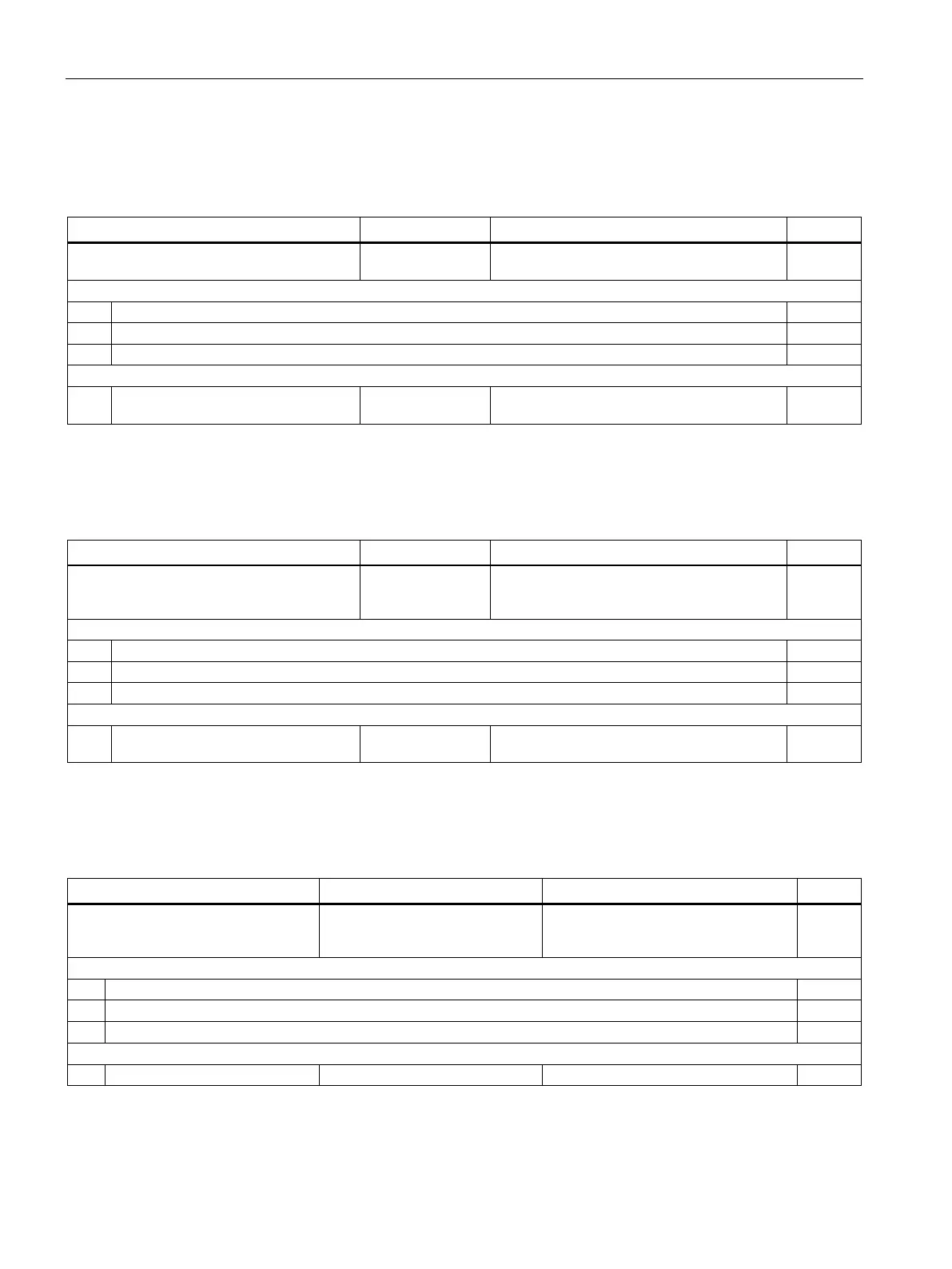
Structure USI = W#16#0001
Table 6- 7 Structure of USI = W#16#0001
Manufacturer-specific diagnostics in case of
overload in an ET 200MP power segment
Followed by 3 reserved bytes
The first power segment with overload starts at slot: <No.>
Structure USI = W#16#0002
Table 6- 8 Structure of the USI = W#16#0002
Manufacturer-specific diagnostics if the
permitted number of power supply modules
Followed by 3 reserved bytes
The first surplus module is located in slot: <No.>
USI structure = W#16#0003
Table 6- 9 USI structure = W#16#0003
Manufacturer-specific diagnostics if
the permitted number of I/O modules
Followed by 3 reserved bytes
The first surplus module is located in slot: <No.>

 Loading...


