Parameters/address space
4.3 Explanation of parameters
Analog input module F-AI 4xI 0(4)..20mA 2-/4-wire HF (6ES7136-6AA00-0CA1)
Manual, 08/2018, A5E41448857-AB
33
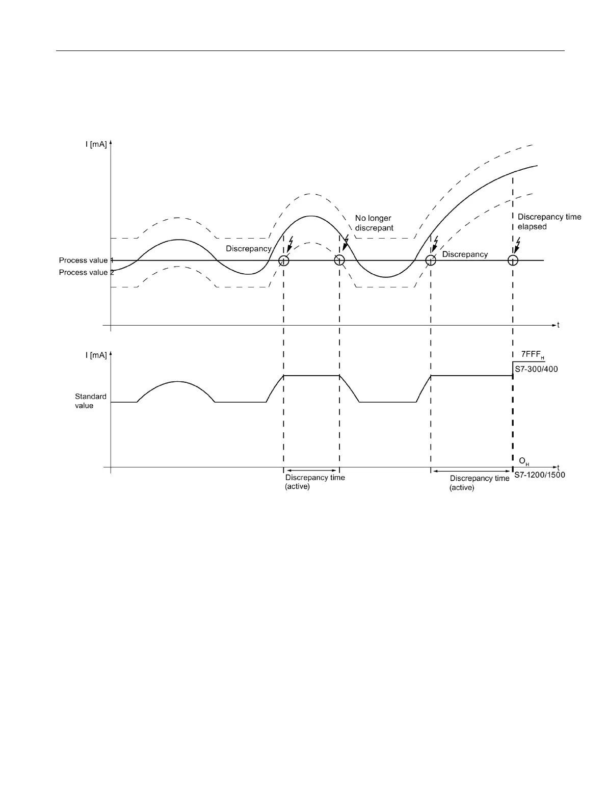
The following diagrams show you the behavior of the discrepancy evaluation when standard
value = MAX.
The upper of the two diagrams shows you the characteristic curve of the two process values.
The dashed line represents the absolute tolerance range configured in this example.
The lower of the two diagrams shows you the standard value signaled to the F-CPU.
In this example, on the first occurrence of a discrepancy, process value 1 is
the
tolerance range again
expiration of the discrepancy time. This means the discrepancy
error is not signaled.
In this example, on the second occurrence of a discrepancy, process value 1 is
the
tolerance range when the discrepancy time expires. As a result, a discrepancy error is
signaled with 7FFF
H
for S7-300/400 F-CPUs or 0 for S7-1200/1500 F-CPUs after expiration
of the discrepancy time. In the PII, the substitute value 0 is set for the safety program.
Discrepancy time (Page 24)
Tolerance window %, absolute (Page 25)
Tolerance window %, relative (Page 26)

 Loading...


