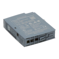
Analog input module F-AI 4xI 0(4)..20mA 2-/4-wire HF (6ES7136-6AA00-0CA1)
6 Manual, 08/2018, A5E41448857-AB
Preface ................................................................................................................................................... 3
1 Documentation guide .............................................................................................................................. 8
2 Product overview .................................................................................................................................. 13
2.1 Properties ............................................................................................................................... 13
3 Connecting ........................................................................................................................................... 16
3.1 Wiring and block diagram ...................................................................................................... 16
4 Parameters/address space ................................................................................................................... 20
4.1 Measurement types and measuring ranges .......................................................................... 20
4.2 Parameters ............................................................................................................................. 20
4.3 Explanation of parameters ..................................................................................................... 22
4.3.1 F-parameters .......................................................................................................................... 22
4.3.2 Parameters of the channels ................................................................................................... 23
4.3.2.1 Interference frequency suppression....................................................................................... 23
4.3.2.2 Evaluation of the sensors ....................................................................................................... 23
4.3.2.3 Standard value ....................................................................................................................... 24
4.3.2.4 Discrepancy time.................................................................................................................... 24
4.3.2.5 Tolerance window %, absolute .............................................................................................. 25
4.3.2.6 Tolerance window %, relative ................................................................................................ 26
4.3.2.7 Parameter assignment of discrepancy analysis for 1oo2 evaluation ..................................... 27
4.3.2.8 Activated ................................................................................................................................ 34
4.3.2.9 Channel failure acknowledge ................................................................................................. 34
4.3.2.10 Measuring range .................................................................................................................... 34
4.3.2.11 Diagnostics: Wire break ......................................................................................................... 35
4.3.2.12 Smoothing .............................................................................................................................. 35
4.4 Address space ....................................................................................................................... 38
5 Applications of the F-I/O module ........................................................................................................... 40
5.1 Application 1: Safety mode SIL3/Cat.3/PLd with 2-wire transducer ...................................... 40
5.2 Application 2: Safety mode SIL3/Cat.4/PLe with 2-wire transducer ...................................... 44
5.3 Application 3: Safety mode SIL3/Cat.3/PLd with 4-wire transducer ...................................... 47
5.4 Application 4: Safety mode SIL3/Cat.4/PLe with 4-wire transducer ...................................... 50
6 Interrupts/diagnostic messages ............................................................................................................. 53
6.1 Status and error display ......................................................................................................... 53
6.2 Interrupts ................................................................................................................................ 56
6.3 Diagnostic messages ............................................................................................................. 58
6.4 Value status ........................................................................................................................... 63

 Loading...


