Installing system components
3.6 Connecting the connection box
Mobile Panels 2nd Generation
Operating Instructions, 09/2018, A5E33876626-AC
67
3. Insert the wire ends into the associated spring-loaded terminal as shown in the figures
below.
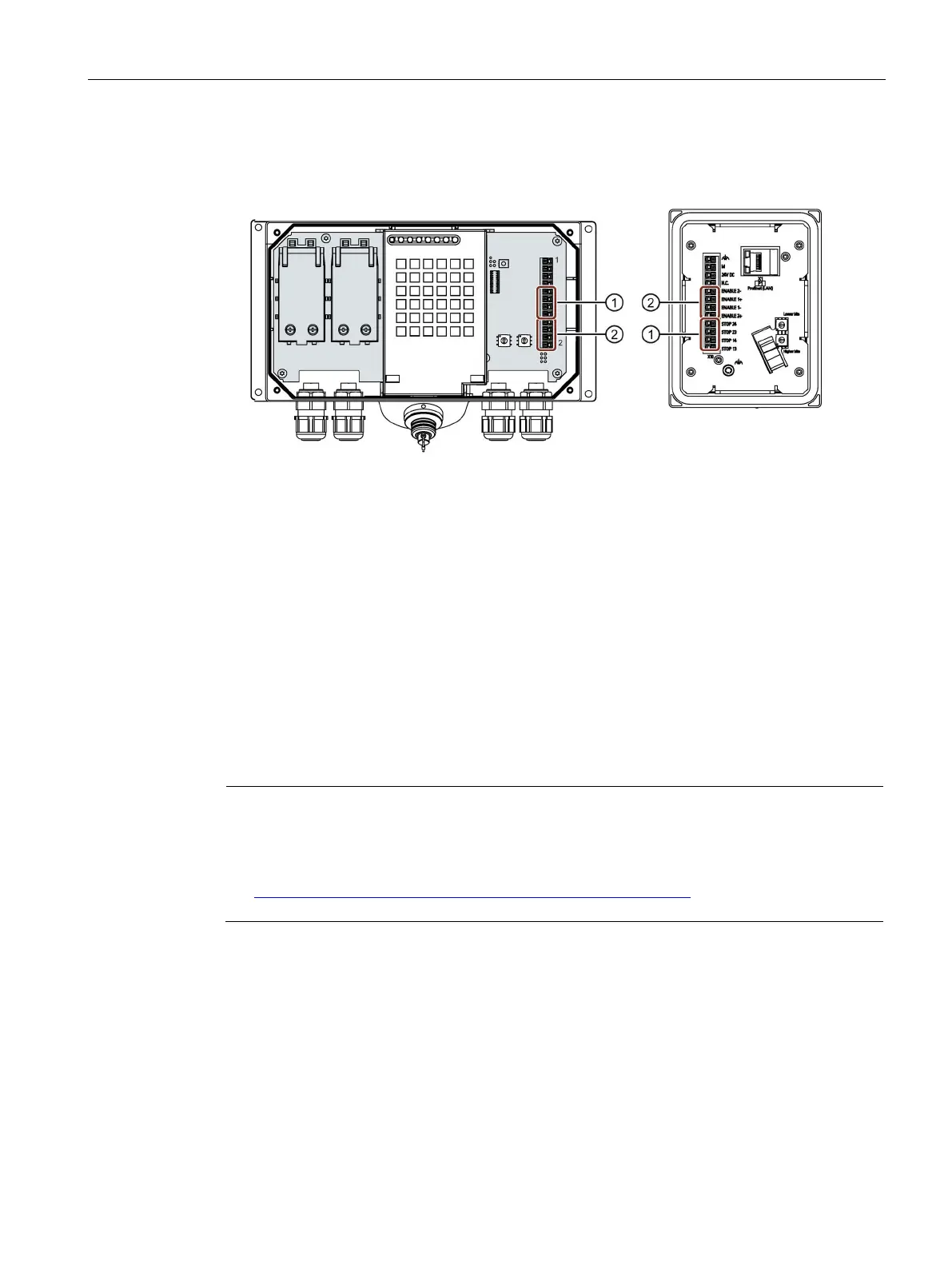
The figure below shows the terminals to be connected to the connection box.
Terminal for the emergency stop / stop button
Terminal for the enabling button
4. Connect the cables. Depending on the connection box, observe the pin assignment of
interface X10:
– Connection box standard and connection box advanced (Page 249)
– Connection box compact (Page 245)
5. For connection box standard and connection box advanced:
When all the required work has been completed in the connection box, close it.
Connecting Ethernet to the connection box
You can connect a controller or other Ethernet devices to the connection box. Compatible
controllers are listed in the section "Communication with controllers (Page 253)".
Only use a switch or comparable device to connect the connection box to public Ethernet
networks.
Follow the information in the "SIMATIC PROFINET system description
(
https://support.industry.siemens.com/cs/us/en/view/19292127)" manual for setting up a
PROFINET network.
 Loading...


