Hardware Information
Release 04/02
7-18
Panel PC 670 Computing Unit, Equipment Manual
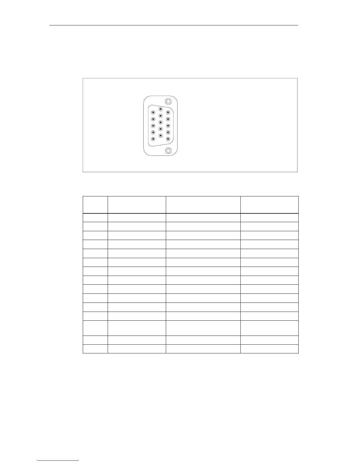
VGA interface
The VGA socket on the computing unit is assigned as follows:
1
5
6
10
11
15
Figure 7-9 VGA Socket Connector
Pin
No.
Short Name Meaning Input/
Output
1 R red Output
2 G green Output
3 B Blue Output
4 - Not assigned -
5 GND Chassis ground -
6 GND Chassis ground -
7 GND Chassis ground -
8 GND Chassis ground -
9 5 V +5V (fused) Output
10 GND Chassis ground -
11 - Not assigned -
12 DDC_DAT Display Data Channel Data Input/Output
13 EXT_H Horizontal synchronizing
pulse
Output
14 EXT_V Vertical synchronizing pulse Output
15 DDC_CLK Display Data Channel Clock Input/Output